EasyManuals Logo
Home>Emerson>DC Drives>Control Techniques EN Series

Emerson Control Techniques EN Series Installation Manual

Emerson Control Techniques EN Series
110 pages
To Next Page IconTo Next Page
To Previous Page IconTo Previous Page
Page #58 background imageLoading...
Page #58 background image
41
Diagnostics and Troubleshooting
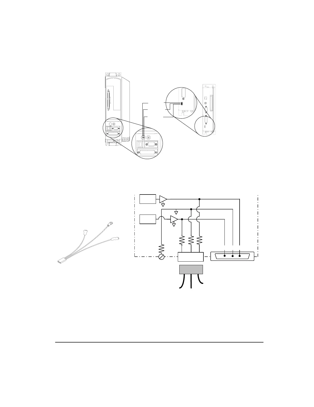
Figure 34: Diagnostic Analog Output Test Points
The DGNE cable was designed to be used with either an oscilloscope or a meter. The wires
are different lengths to avoid shorting to each other. However, if signals do get shorted to
GND, the drive will not be damaged because the circuitry is protected.
Figure 35: Diagnostic Cable (DGNE) Diagram
Channel #2
Channel #1
Analog GND
E Series Drive
Epsilon Drive
10 Ohm
10 Ohm
Yellow
Black
(GND)
Blue
D/A
D/A
DGNE Cable
Command Connector
DGNE Cable
2GND1
2
1
GND
44 29 43
Pin #'s
Artisan Technology Group - Quality Instrumentation ... Guaranteed | (888) 88-SOURCE | www.artisantg.com

Other manuals for Emerson Control Techniques EN Series

Questions and Answers:

Question and Answer IconNeed help?

Do you have a question about the Emerson Control Techniques EN Series and is the answer not in the manual?

Emerson Control Techniques EN Series Specifications

General IconGeneral
BrandEmerson
ModelControl Techniques EN Series
CategoryDC Drives
LanguageEnglish

Related product manuals