98
Epsilon Eb and EN Drives Reference Manual
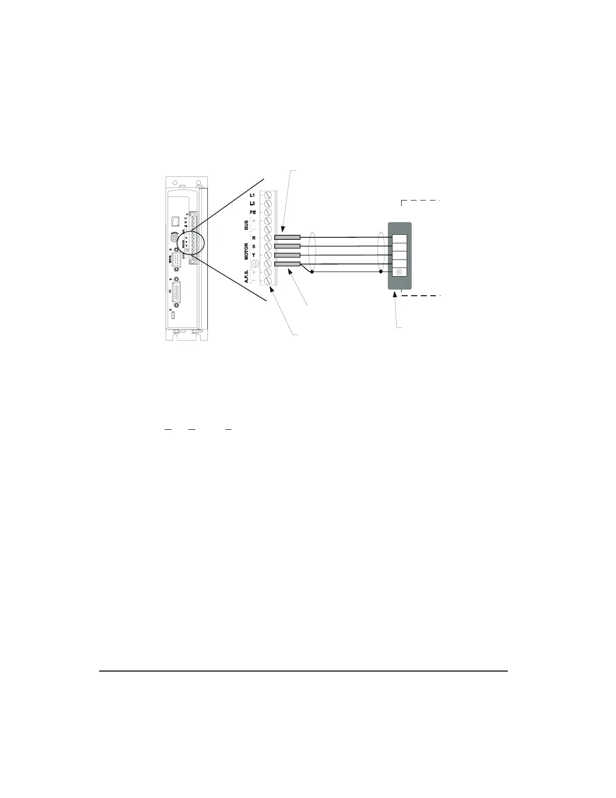
Figure 67: Epsilon Motor Power Wiring Diagram
Motor Feedback Wiring
Encoder feedback connections are made with the CFCS cable. This cable has an MS style
connector on the motor end and a 26-pin high density “D” connector on the drive end.
For A, A
, B, B and Z, Z pairs, the CFCS cable uses low capacitance (~10 pf/ft) wire to get a
characteristic impedance of 120 ohms. This impedance match is important to minimize signal
loss and ringing.
Connector Shell
R
S
T
Ground
Motor Power
Connection
B
C
D
Front View
Tighten screws to 5 lb-in.
Important:
PE ground
should connect to drive
and motor only. Nothing
should be connected
between these devices.
J1
Brown
Black
Blue
Green/Yellow
Shield
2" and 3" motor cable
connector (CMDS-xxx cable)
PT06A-16-8SSR
Wire crimp ferrules are recommended:
For Motor ground lead use -
Pheonix Contact P/N AI-TWIN 2x1, 5-8 Bk/32 00 82 3
American Electrical/DigiKey 1381015/288-1130-ND
For motor phase leads use -
Phoenix Contact P/N AI 1, 5-8 RD/ 32 01 13 6
ALTEC P/N H1.5/14 2204.0 Pk/100
Artisan Technology Group - Quality Instrumentation ... Guaranteed | (888) 88-SOURCE | www.artisantg.com
 Loading...


