Section 3 - Grounding & Isolation Page 3-9 S1400CW
• all conductive tubing that runs between the pipeline and mounting valve manifold
and/or the units multivariable pressure transducer
• all conductive connections or tubing runs between the ControlWave EFM/GFC and
turbine meter, pulse transducer, or any input other device that is mounted on the
pipeline
• any Temperature Transducer, Pressure Transmitter, etc. and their mount/interface to
the pipeline
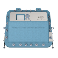
Figure 3-9 - ControlWave EFM (Installation is similar to EFM/GFC/XFC)
Direct Mount Installation (with Cathodic Protection)
The ground conductor connects between the ControlWave EFM/GFC/XFC’s Ground Lug
and a known good earth ground. Connect the cases of Temperature Transducers, Pressure
Transmitters, etc., to the known good earth ground. If the mounting 2-inch pipe is in
continuity with the pipeline it will have to be electrically isolated from the ControlWave
EFM/GFC/XFC. Use a strong heat-shrink material such as RAYCHEM WCSM 68/22 EU
3140. This black tubing will easily slip over the 2-inch pipe and then after uniform heating
(e.g., with a rose-bud torch) it electrically insulates and increases the strength of the pipe
stand.