EasyManua.ls Logo

Emerson 8800C - User Manual

Emerson 8800C
160 pages
Print Icon
To Next Page IconTo Next Page
Loading...
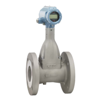
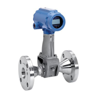
Model 8800C and Model 8800A
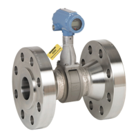
Smart Vortex Flowmeter
00809-0100-4003
English
Rev. JA

Table of Contents

Questions and Answers

  • S
    Scott CameronAug 14, 2025
    How to solve communication problems with HART-based Communicator Emerson 8800C Measuring Instruments?
    • A
      Adrian WilliamsAug 15, 2025
      To troubleshoot communication issues with your HART-based Communicator, start by checking for a minimum of 12 V dc at the transmitter terminals. Then, check the communications loop. Ensure there's a loop resistor (250 to 1000 ohms) in place. Verify the transmitter is not in multidrop or burst mode. If you have a three-wire pulse installation, remove the pulse connection. If these steps don't resolve the issue, consider replacing the electronics.
  • C
    Cassandra HayesAug 17, 2025
    What to do if there is flow in pipe but no output from Emerson 8800C?
    • J
      jonathan95Aug 18, 2025
      First, ensure the meter is installed correctly, with the arrow indicating the direction of process flow. Next, perform basic checks for an incorrect 4–20 mA output. After that, check and correct configuration parameters in the following order: K-factor, service type, materials, units, process temperature, damping value, 4–20 mA trim, meter body number, density, pulse mode, pulse scaling, line size, pipe diameter, LRV, URV, LP corner, trigger level, and low flow cutoff. Also, verify that the flow is within measurable flow limits. Finally, refer to Appendix E: Electronics Verification for the electronics verification procedure.
  • L
    Lisa MooreAug 21, 2025
    What to do if Emerson 8800C Measuring Instruments shows incorrect 4–20 mA Output?
    • M
      Michelle HardingAug 21, 2025
      If you're seeing an incorrect 4–20 mA output, first check for 12 V dc at the transmitter terminal. Then, check the URV, LRV, Density, Special Units, and LFC, and compare these inputs with the sizing program results, correcting the configuration as needed. Finally, perform a 4–20 mA loop test.
  • Y
    Yvette ButlerAug 25, 2025
    Why is Emerson 8800C giving a 50/60 Hz measurement?
    • M
      michaelkirbyAug 25, 2025
      A 50/60 Hz measurement may indicate electrical or magnetic interference. Ensure the electronics mounting screws (3) are securely installed. Check the meter ground and measure voltage levels between the 4–20 mA and pulse outputs and the electronics housing, ensuring the common mode voltage is less than 30 Vrms. If the meter is near a large motor or electric furnace, try different orientations to reduce noise, ensuring magnetic fields are less than 5 gauss. For remote mount installations, try an integral mount to see if the problem is corrected, and measure AC voltage from the electronics housing to the SMA connector, ensuring the voltage is less than 1Vrms.
  • J
    Jaclyn WilliamsAug 27, 2025
    What to do for Emerson Measuring Instruments output with no actual flow?
    • A
      Adrian WongAug 27, 2025
      First, perform basic checks for an Incorrect 4–20 mA Output. Then, check and correct configuration parameters in this order: K-factor, service type, materials, units, process temperature, damping value, 4–20 mA trim, meter body number, density, pulse mode, pulse scaling, line size, pipe diameter, LRV, URV, LP corner, trigger level, low flow cutoff. After that, check sizing to ensure flow is within measurable flow limits. Finally, using a HART-based communicator, read the shedding frequency.
  • R
    Robert ReedAug 31, 2025
    How to troubleshoot application problems with Emerson 8800C?
    • S
      Stephanie SotoAug 31, 2025
      To address application problems, start by calculating the expected frequency. If the actual frequency is the same, check the configuration. Then, verify that the application meets the viscosity and specific gravity requirements for the line size. Finally, recalculate the back pressure requirement and, if necessary and possible, increase back pressure, flow rate, or operating pressure.
  • D
    Dawn PetersonSep 3, 2025
    Why is Emerson Measuring Instruments having a vibration problem?
    • M
      Mark DavisSep 3, 2025
      To address vibration issues, try adjusting the signal processing parameters. If that doesn't work, rotate the meter 90 degrees. As a final measure, add support to the line near the meter to dampen the vibration.
  • A
    Anthony AtkinsonSep 6, 2025
    What to do if Emerson 8800C has incorrect pulse output?
    • J
      Jimmy FergusonSep 7, 2025
      First, check that the 4–20 mA output is correct. Then, check the pulse counter specifications. Next, check the pulse mode and scaling factor, ensuring the scaling factor is not inverted. Also, check for corrosion on the terminal block. If necessary, replace the electronics. Finally, see Appendix E: Electronics Verification for the electronics verification procedure.
  • S
    Stephanie StevensSep 10, 2025
    How to troubleshoot electronics issues in Emerson 8800C Measuring Instruments?
    • K
      Kathleen CoxSep 12, 2025
      To troubleshoot electronics, run a self-test using the Model 268/HART Communicator. You can also insert a test signal using a sensor simulator. Check the configuration, LFC, trigger level, and the relationship between standard and actual flow. If problems persist, consider replacing the electronics.

Summary

SECTION 2 Installation

SAFETY MESSAGES

Details safety precautions for installation, including warnings about explosive atmospheres.

Commissioning

Outlines the process of commissioning the flowmeter before operation for proper setup.

HAZARDOUS LOCATIONS

Explains explosion-proof and intrinsically safe certifications and markings.

SECTION 3 Operation

DIAGNOSTICS;SERVICE

Functions to verify proper operation or troubleshoot suspect component failure.

SECTION 4 Hardware and Software Maintenance and Troubleshooting

Troubleshooting Tables

Provides summarized suggestions for common operational problems and symptoms.

Advanced Troubleshooting

Details features for looking inside electronics for troubleshooting inaccurate readings.

HARDWARE REPLACEMENT

Procedures for disassembling and assembling hardware components for replacement.

Replacing the Terminal Block in the Housing

Step-by-step instructions for replacing the terminal block in the housing.

Replacing the Electronics Boards

Procedures for replacing damaged or dysfunctional electronics boards.

Replacing the Electronics Housing

Describes the process for easily replacing the electronics housing when necessary.

Replacing the Sensor

Detailed procedures for replacing the sensor if a problem is determined to exist.

Appendix A Reference Data

Hazardous Locations Certifications

Lists FM, CSA, and ATEX approvals for hazardous locations.

Appendix D Model 268 Communicator

Diagnostics Messages

Guides on diagnostic messages from the Model 268 and their descriptions.

Appendix E Electronics Verification

Safety Messages

Emphasizes safety precautions for electronics verification procedures.

Electronics Verification

Outlines methods for verifying electronics functionality using simulation or external signals.

Emerson 8800C Specifications

General IconGeneral
TypeVortex Flow Meter
Line Size1 to 12 in (25 to 300 mm)
Output4-20 mA, HART, Foundation Fieldbus
MaterialStainless Steel
Pressure RangeUp to 100 bar (1450 psi)
Process ConnectionFlanged, Wafer
Electrical ConnectionM20
Operating Temperature-40°C to 85°C (-40°F to 185°F)
Housing MaterialAluminum or Stainless Steel
Diaphragm MaterialStainless Steel

Related product manuals