Rosemount Model 8800C Vortex Flowmeter
2-12
Flanged-Style
Flowmeter Mounting
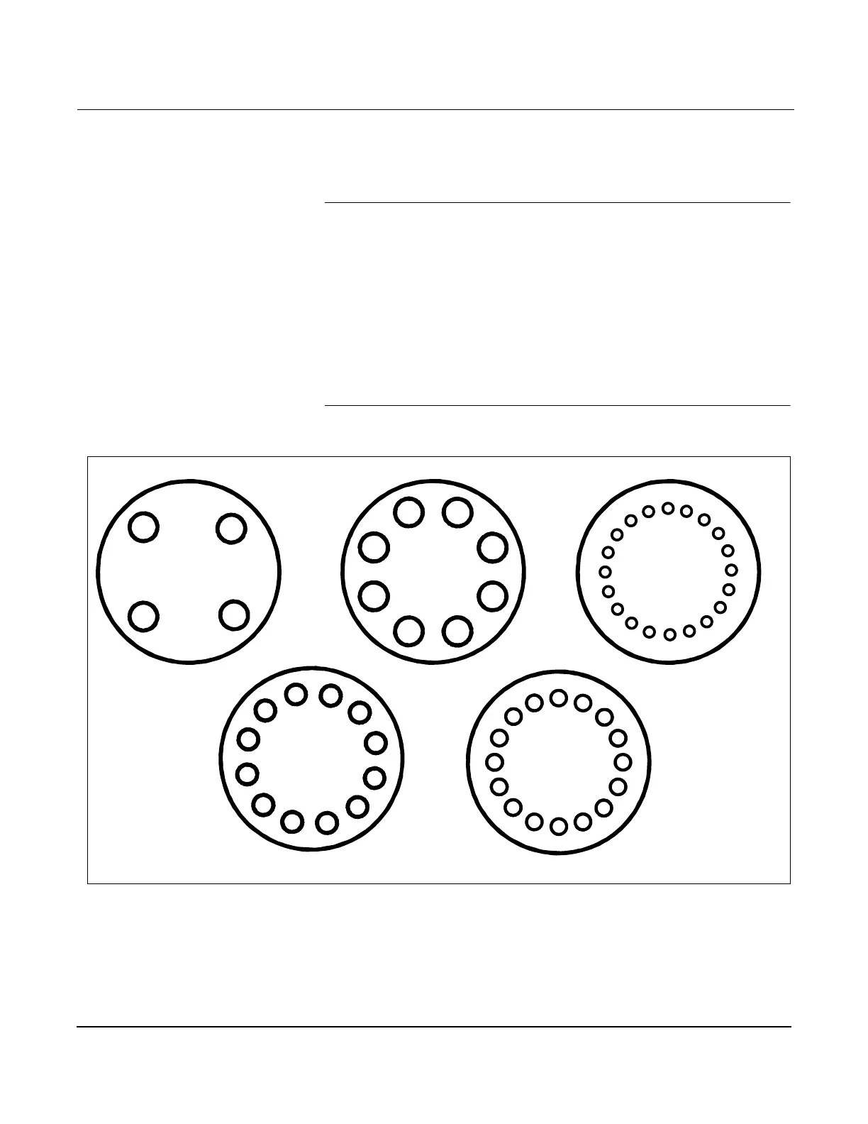
Physical mounting of a flanged-style flowmeter is similar to installing a
typical section of pipe. Conventional tools, equipment, and accessories
(such as bolts and gaskets) are required. Tighten the nuts following the
sequence shown in Figure 2-9.
NOTE
The required bolt load for sealing the gasket joint is affected by several
factors, including operating pressure and gasket material, width, and
condition. A number of factors also affect the actual bolt load resulting
from a measured torque, including condition of bolt threads, friction
between the nut head and the flange, and parallelism of the flanges. Due
to these application-dependent factors, the required torque for each
application may be different. Follow the guidelines outlined in the ASME
Pressure Vessel Code (Section VIII, Division 2) for proper bolt tightening.
Make sure the flowmeter is centered between flanges of the same
nominal size as the flowmeter.
Figure 2-9. Flange Bolt Torquing Sequence
8800-0088A
1
3
4
2
3
8
1
5
2
7
6
4
14
18
9
1
9
5
11
3
19
15
7
13
17
2
10
6
12
4
20
16
8
3
7
2
6
10
4
8
12
1
5
16
1
9
5
11
3
13
7
15
2
10
6
12
4
14
8
16-Bolt
12-Bolt
8-Bolt
4-Bolt
20-Bolt
11