What does red light mean on Emerson Control Unit?
- TTyler RileyJul 26, 2025
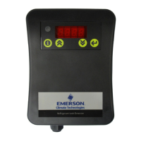
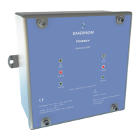
If there is a transaction error/timeout or the network stopped on your Emerson Control Unit module, the indicator light will be red.
What does red light mean on Emerson Control Unit?
If there is a transaction error/timeout or the network stopped on your Emerson Control Unit module, the indicator light will be red.
Details the manual's content and required user knowledge.
Lists other relevant documents for further information.
Explains the module's role as a gateway and its architecture.
Describes the standard web pages for configuration and monitoring.
Mentions optional web pages for specific application needs.
Lists all required hardware and software for installation.
Step-by-step procedure for installing with MVD Direct Connect.
Procedure for configuring the transmitter for Modbus communication.
Key steps for physical installation and network configuration.
Details wiring for power supply and Modbus serial connections.
Explains the function and settings of the module's dip switches.
Procedures for setting IP address, subnet mask, and gateway.
Steps for integrating the module into the Ethernet network control system.
Table detailing Modbus terminal assignments for various transmitters.
Guide for installing and using the configuration software.
Specifies hardware and software prerequisites for the config tool.
Procedure for installing the configuration tool from the resource CD.
Steps for configuring the module via its web interface.
Defines how to configure the module's TCP/IP parameters for network participation.
Using the web interface to set IP address, gateway, and subnet.
How physical switches lock network settings and determine IP address.
Table illustrating IP addresses based on switch combinations.
Using the tool to manage network configurations.
Restricting access to the module's web server by IP address.
Configuration parameters for the Modbus serial interface.
Details on communication ports and user authentication for the web server.
Functionality and tasks available through the module's web pages.
Procedure for integrating with RSLogix 5000/Studio 5000 version 20+.
Requirements before integrating with Rockwell software.
Step-by-step guide for integrating with newer Rockwell versions.
Options for managing the module's connection type in Rockwell.
Procedure for integrating with RSLogix 5000 version 19 or earlier.
Step-by-step guide for older Rockwell versions using generic modules.
Table of standard parameters for Rockwell integration.
Rockwell integration parameters for concentration measurement.
Rockwell integration parameters for petroleum measurement.
Explains the meaning of various LED status lights on the module.
Details status LEDs for network and device functions.
Addresses frequent operational issues and their solutions.
Troubleshoots issues with transferring configuration data.
Diagnoses problems indicated by the Config Line LED turning red.
Resolving issues when the module is unreachable via its serial port.
Troubleshooting causes of slow or degraded module performance.
Diagnosing and fixing issues with Modbus serial communication.
Troubleshooting why process variables show zero or are not displayed.
Pin configuration for the RJ45 Ethernet port.
Pin configuration for the power input connector.
Steps for installing the configuration tool.
Specifies hardware and software prerequisites for the config tool.
Procedure for installing the configuration software.
Explanation of the RS-485 physical layer for Modbus communication.
Technical explanation of bias resistors in RS-485 networks.
Technical details on RS-485 network termination resistors.
Specific pinout for the EtherNet/IP connector on the module.
Illustrates a common wiring setup for the module.
Lists and describes the object classes supported by the module.
Provides in-depth information on specific objects and their attributes.
Details the object responsible for device identification and general information.
Lists the services available for objects and instances.
Describes attributes associated with object classes.
Describes attributes associated with object instances.
Explains the meaning of different bits within the device status word.
Details the functionality and behavior of the reset service.
Describes the Message Router object used for messaging connections.
Describes the Assembly Object for binding I/O data.
Specific input assembly attributes for I/O data.
Specific output assembly attributes for I/O data.
Details the Port Object, which describes communication ports.
Describes the object for TCP/IP related settings.
Details the Ethernet Link Object for diagnostic information.
Describes the Diagnostic Object for fieldbus interface diagnostics.
Object for accessing input data acyclically.
Object for accessing output data acyclically.
Details the input and output data structures for various configurations.
Maps input data for standard configuration.
Maps output data for standard configuration.
Detailed input parameter mapping with trigger bytes.
Explanations for various device status words.
Detailed output parameter mapping with trigger bytes.
Maps input data for concentration measurement.
Maps output data for concentration measurement.
Detailed input parameters for concentration measurement.
Explanations for various device status words.
Detailed output parameters for concentration measurement.
Maps input data for petroleum measurement.
Maps output data for petroleum measurement.
Detailed input parameters for petroleum measurement.
Explanations for various device status words.
Detailed output parameters for petroleum measurement.
Describes services for retrieving and setting attribute values.
Details the service for reading a single attribute.
Details the service for writing a single attribute.
Defines the various data types used in the module's communication.
Lists codes and integer values for units and parameters.
Codes for different units of mass flow measurement.
Codes for mass totalizer and inventory units.
Codes for various liquid volume flow units.
Codes for liquid volume totalizer and inventory units.
Codes for gas standard volume flow units.
Codes for gas standard volume totalizer and inventory units.
Codes for different density measurement units.
Codes for various temperature measurement units.
Codes for pressure and differential pressure units.
Codes for concentration measurement units.
Codes for derived concentration variables.
Codes specifying API table types.
Codes for fixed output values in Smart Meter Verification.
Codes for enabling and configuring Smart Meter Verification.
States indicating the progress of the meter verification algorithm.
Status bits indicating the state of Smart Meter Verification.
Codes indicating why Smart Meter Verification was aborted.
States of verification when an abort occurs.
Details the meaning of various status words and their bit meanings.
Explanation of the bits within Status Word 1.
Explanation of the bits within Status Word 2.
Explanation of the bits within Status Word 3.
Explanation of the bits within Status Word 4.
Explanation of the bits within Status Word 5.
Explanation of the bits within Status Word 6.
Explanation of the bits within Status Word 7.
Details the module's physical dimensions and housing.
Specifies power supply requirements and consumption.
Describes operating temperature and humidity ranges.
Lists electromagnetic compatibility standards the module meets.
Details galvanic isolation requirements for the Modbus interface.
| Category | Measuring Instruments |
|---|---|
| Manufacturer | Emerson |
| Brand | Micro Motion |
| Type | Coriolis Flow Meter |
| Output | 4-20 mA, HART, Foundation Fieldbus, Profibus, Modbus |
| Power Supply | 24 V DC |
| Material | Stainless Steel, Hastelloy |
| Process Connection | Flanged, Threaded |
| Certifications | ATEX, IECEx, CSA, SIL |
| Pressure Rating | Varies by model; up to 10, 000 psi (690 bar) |
| Temperature Range | Varies by model; -400 to 750°F (-240 to 400°C) |


