The bias resistors forms a voltage divider, forcing the voltage between the differential pair
to be higher then the threshold for the serial receivers, typically >200 mV. Note that bias
resistors shall only be installed on one node. Installing bias resistors on several nodes may
compromise the signal quality on the network and cause transmission problems.
A.4.2 Termination
To avoid reflections on the serial lines, it is important to properly terminate the sub-
network by placing termination resistors between the serial receivers near the end nodes.
Additionally, if the distance from the EtherNet/IP Module to the transmitter is greater than
100 feet, Micro Motion recommends adding the termination resistors.
The resistor value should ideally match the characteristic impedance of the cable, typically
100 to 120 Ω.
A.4.3
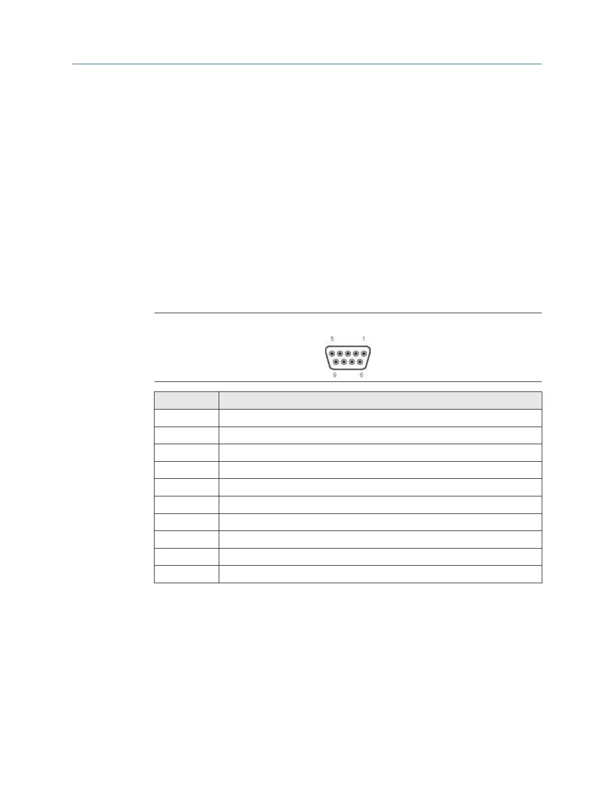
Pin assignments (EtherNet/IP Module)
Figure A-1: Female connection
Pin Description
1 5 V output (100mA max)
2 Unused
3 Unused
4 Unused
5 Ground
6 Unused
7 Unused
8 RS-485/A (Tx+)
9 RS-485/B (Tx–)
(housing) Cable shield
User Guide Connector pin assignments
MMI-20019808 January 2019
User Guide 33