2 Installation
2.1 Components
Ensure that you have all required components:
• Micro Motion EtherNet/IP Module
• Power connector
• Micro Motion EtherNet/IP Resource CD
— Micro Motion EtherNet/IP Module User Manual
— EDS file
— MicroMotion Ethernet Config Tool
• Configuration cable
• Modbus serial cable and connector (included)
• Ethernet cable and connector (not included)
2.2 Set up the module with MVD Direct Connect
Use this procedure only if you are installing the module with MVD Direct Connect.
Procedure
1. Mount and wire the core processor and barrier.
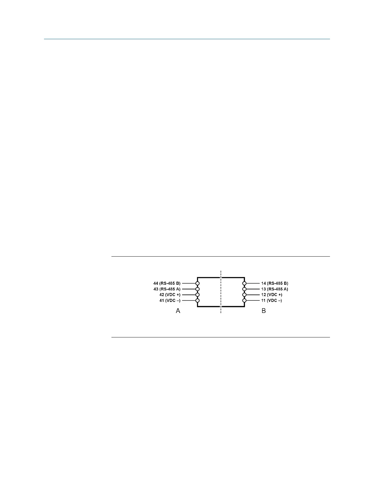
Figure 2-1: Barrier
A. I.S. terminals for connection to core processor
B. Non-I.S. terminals for connection to remote host and power supply
2. Power up the core processor and barrier.
3. Set the Modbus address on the core processor to 1.
Postrequisites
Continue to Mount, wire, and set the network settings.
User Guide
Installation
MMI-20019808 January 2019
User Guide 9