Do you have a question about the Emerson Micro Motion 2500 and is the answer not in the manual?
Introduces the manual and lists supported transmitters for Series 1000 and 2000.
Emphasizes reading safety messages for personnel and equipment protection.
Explains how to identify transmitter type, installation, and output board from the model number.
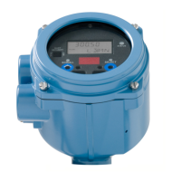
Introduces the transmitter display and its basic configuration and management functionality.
Illustrates and labels the components of the transmitter display.
Explains how to navigate the transmitter display using the Scroll and Select optical switches.
Details how to view process variable data and access transmitter menus for configuration.
Details password usage for controlling access to menu functions.
Guides on entering configuration values like meter factors using the display.
Introduces ProLink II as a configuration tool and outlines chapter topics.
Lists necessary hardware and software for using ProLink II with Series 1000/2000 transmitters.
Explains backing up and restoring transmitter configurations using ProLink II.
Details connection options for 1700/2700 transmitters using ProLink II.
Details connection options for 1500/2500 transmitters using ProLink II.
Introduces HART Communicators and outlines chapter topics for connecting to transmitters.
Lists communicator models and their support for Series 1000/2000 transmitters.
Details connecting the communicator to transmitter mA/HART terminals or a HART network.
Explains conventions used in the manual for communicator procedures.
Describes initial procedures for installing and configuring the flowmeter correctly.
Details the process of applying power to the flowmeter and initial diagnostic routines.
Explains how to verify outputs and check mA trimming needs with a loop test.
Guides on trimming mA outputs for accurate signal range between transmitter and device.
Explains establishing the flowmeter's zero reference point when there is no flow.
Describes configuration procedures typically required for first-time transmitter installation.
Explains adjusting the transmitter to compensate for unique sensor traits.
Refers to a supplement for information and instructions on channel configuration.
Explains how to configure units for process variables like mass flow and density.
Explains setting a baseline for meter verification with enhanced core processors.
Introduces how to use the transmitter in everyday operation, covering key topics.
Lists special applications like Petroleum measurement and Enhanced density.
Details how to view process variables using display, ProLink II, or Communicator.
Describes how to view transmitter status and alarms via LED, display, or software.
Details how to acknowledge alarms using ProLink II or the display.
Shows control methods for totalizers and inventories across different tools.
Introduces optional configuration parameters that may or may not be used.
Details special functionality for measuring standard volume flow of gases using ProLink II.
Guides on creating non-standard units for mass and volume flow.
Explains API parameters for calculations in petroleum measurement.
Explains user-defined values below which the transmitter reports zero for a process variable.
Describes damping values for smoothing measurement fluctuations.
Describes the rate at which the transmitter polls the sensor for process data.
Controls how the transmitter reports flow rate and adds/subtracts it from totalizers.
Details ways the transmitter reports faults and how severity controls behavior.
Guides on enabling/disabling display functions and setting display parameters.
Details device settings for describing flowmeter components.
Explains sensor parameters used to describe the sensor component.
Explains the write-protect mode to prevent configuration changes.
Introduces procedures for pressure compensation, temperature compensation, and polling.
Explains compensating for pressure effects on sensor flow tubes and density sensitivity.
Explains using external temperature values for more accurate calculations.
Explains configuring polling for HART protocol over Bell 202 physical layer.
Introduces procedures for meter verification, validation, and calibration.
Compares and defines meter verification, validation, and calibration procedures.
Outlines procedures for performing meter verification tests.
Guides on measuring process fluid and comparing with flowmeter's reported value.
Details calibration points and procedures for density calibration.
Explains the two-part procedure for temperature offset and slope calibration.
Introduces transmitters approved for custody transfer and their model code patterns.
Explains configuring NTEP or OIML compliance for weights and measures.
Details restrictions on functionality and output behavior in custody transfer configurations.
Describes the factory default security breach mode and its implications.
Explains placing the transmitter into secure mode for service and its security features.
Provides guidelines and procedures for troubleshooting the meter.
Lists troubleshooting topics and their corresponding sections in the chapter.
Directs users to contact customer service for unresolved issues.
Provides troubleshooting steps when the transmitter does not operate at all.
Guides on troubleshooting communication issues with the transmitter.
Addresses issues related to zero or calibration procedure failures.
Explains how to identify and address fault conditions indicated by outputs or alarms.
Provides remedies for issues with mA, frequency, or discrete outputs/inputs.
Explains using simulation mode to test system response and locate noise sources.
Provides procedures to check transmitter installation for wiring issues.
Explains parameters to suppress extreme process variable changes due to slugs.
Addresses incorrect characterization causing inaccurate output values.
Explains using test points to diagnose sensor failure or overrange conditions.
Describes checking the core processor LED and performing resistance tests.
Explains testing sensor coils and RTD for alarms and out-of-range conditions.
Provides default values for transmitter parameters and valid ranges.
Lists default values and ranges for commonly used transmitter settings.
Provides illustrations of different flowmeter installations and components.
Details installation types for Model 1500/2500 transmitters.
Details installation types for Model 1700/2700 transmitters.
Introduces menu flowcharts for the Model 1500 AN transmitter.
Shows ProLink II main and configuration menu structures.
Provides Communicator menu flowcharts for process variables, diagnostics, and setup.
Introduces menu flowcharts for the Model 2500 CIO transmitter.
Shows ProLink II main and configuration menu structures.
Provides Communicator menu flowcharts for process variables, diagnostics, and setup.
Introduces menu flowcharts for the Model 1700/2700 AN transmitter.
Shows ProLink II main and configuration menu structures.
Provides Communicator menu flowcharts for process variables, diagnostics, and setup.
Provides display menu flowcharts for totalizers, alarms, maintenance, and simulation.
Introduces menu flowcharts for the Model 1700/2700 IS transmitter.
Shows ProLink II main and configuration menu structures.
Provides Communicator menu flowcharts for process variables, diagnostics, and setup.
Provides display menu flowcharts for totalizers, alarms, maintenance, and simulation.
Introduces menu flowcharts for the Model 2700 CIO transmitter.
Shows ProLink II main and configuration menu structures.
Provides Communicator menu flowcharts for process variables, diagnostics, and setup.
Provides display menu flowcharts for totalizers, alarms, maintenance, and simulation.
Provides information on codes and abbreviations used on the transmitter display.
Documents the change history of the Series 1000/2000 transmitter software.
Index entries for numerical items.
Index entries for the letter A.
Index entries for the letter B.
Index entries for the letter C.
Index entries for the letter D.
Index entries for the letter E.
Index entries for the letter F.
Index entries for the letter G.
Index entries for the letter H.
Index entries for I/O.
Index entries for installation types.
Index entries for inventories.
Index entries for language.
Index entries for locking clamps.
Index entries for loop current mode.
Index entries for low pickoff voltage.
Index entries for LRV.
Index entries for mA output.
Index entries for mass flow.
Index entries for measurement units.
Index entries for meter factors.
Index entries for meter validation.
Index entries for meter verification.
Index entries for Micro Motion customer service.
Index entries for Modbus address.
Index entries for NTEP.
Index entries for OIML.
Index entries for optical switches.
Index entries for output saturation.
Index entries for output wiring.
Index entries for parity.
Index entries for password.
Index entries for petroleum measurement application.
Index entries for pickoff values.
Index entries for pickoff voltage.
Index entries for plus sign on display.
Index entries for Pocket ProLink.
Index entries for polarity.
Index entries for polling.
Index entries for power supply.
Index entries for pre-configuration worksheet.
Index entries for pressure.
Index entries for primary mA output.
Index entries for process variable.
Index entries for protocol.
Index entries for PV.
Index entries for QV.
Index entries for range.
Index entries for receiving device.
Index entries for recording process variables.
Index entries for remote core processor components.
Index entries for resistance.
Index entries for restricted I/O.
Index entries for RF interference.
Index entries for RS-485 parameters.
Index entries for safety.
Index entries for saving ProLink II configuration files.
Index entries for scaling.
Index entries for scroll rate.
Index entries for secondary mA output.
Index entries for secure mode.
Index entries for security breach.
Index entries for sensor.
Index entries for sensor simulation mode.
Index entries for Series 1000 and 2000.
Index entries for short to case test.
Index entries for short zero.
Index entries for signal converter.
Index entries for simulation mode.
Index entries for single-setpoint event model.
Index entries for slug flow.
Index entries for slugs.
Index entries for Smart Meter Verification.
Index entries for special applications.
Index entries for special measurement units.
Index entries for special mode.
Index entries for standard volume flow measurement for gas.
Index entries for status alarms.
Index entries for status LED.
Index entries for stop bits.
Index entries for SV.
Index entries for temperature.
| Category | Transmitter |
|---|---|
| Manufacturer | Emerson |
| Model | Micro Motion 2500 |
| Measurement Principle | Coriolis |
| Output Options | 4-20 mA, Pulse, Frequency |
| Communication Protocol | HART, FOUNDATION Fieldbus |
| Display | LCD |
| Operating Temperature | -40 to 60 °C (-40 to 140 °F) |
| Enclosure Rating | NEMA 4X, IP66 |
| Accuracy | ±0.10% of flow rate |
| Ambient Temperature Range | -40 to 140 °F (-40 to 60 °C) |