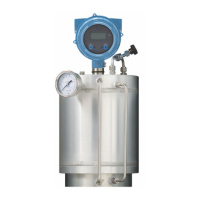
Figure 2-3: Snap off
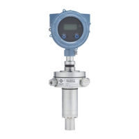
3. Wire the EtherNet/IP Module to power (24 VDC).
Figure 2-4: Power connections on the EtherNet/IP module
A. 24 VDC
B. Ground
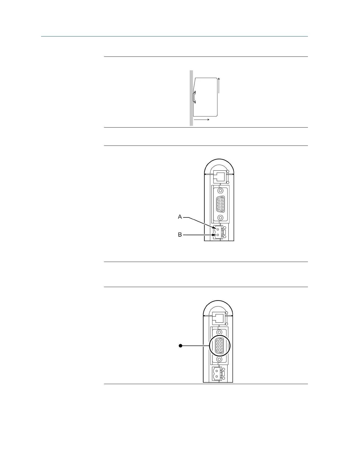
4. Install the Modbus serial cable between the EtherNet/IP Module and the RS-485
terminals on the transmitter (or the I.S. barrier, if present).
Figure 2-5: Modbus serial connector on the EtherNet/IP module
See Modbus terminals and Pin assignments (EtherNet/IP Module).
5. Set the configuration dip switches on the EtherNet/IP module as follows:
User Guide
Installation
MMI-20019808 January 2019
User Guide 11