2-33
Installation
OPTIONS
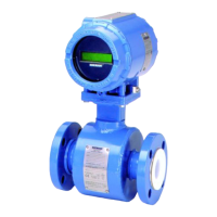
LCD INDICATOR The LCD indicator (option M5) provides local indication of the output
and abbreviated diagnostic messages governing operation of the
flowmeter. The indicator is located on the circuit side of the flowmeter
electronics, leaving direct access to the signal terminals. An extended
cover is required to accommodate the indicator. Figure 2-26 shows the
flowmeter fitted with the LCD indicator and extended cover.
Figure 2-26. Model 8800C with Optional Indicator
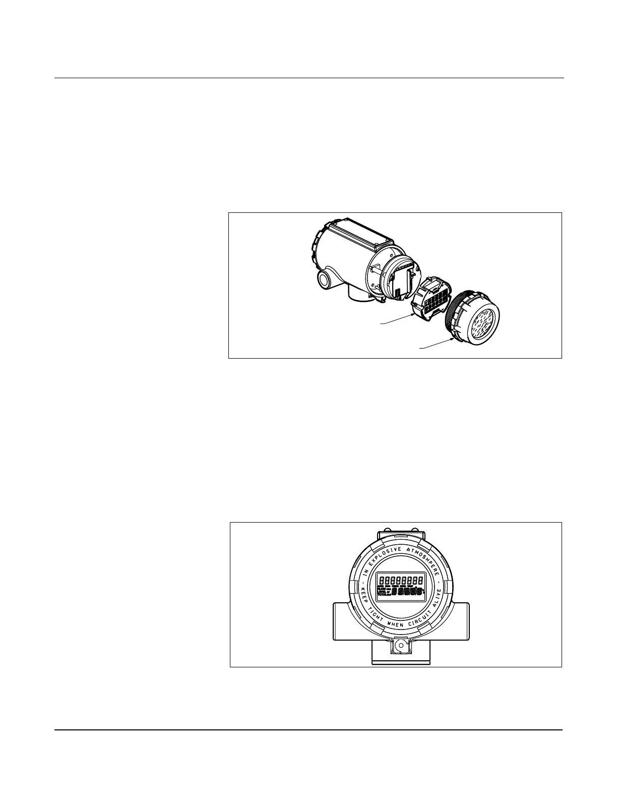
The indicator features an eight-character (and five alphanumeric)
liquid crystal display that gives a direct reading of the digital signal
from the microprocessor. During normal operation, the display can be
configured to alternate between four readings:
1. Primary flow variable in engineering units
2. Percent of range
3. Totalized flow
4. 4–20 mA electrical current output
Figure 2-27 shows the indicator display with all segments lit.
Figure 2-27. Optional Liquid Crystal Display
A HART-based communicator can be used to change the engineering
units displayed on the indicator. (See Section 3: Operation for more
information).
Meter Cover
Meter Assembly
8800-0000B01A
8800-0463B06A