Appendix
A-1
Appendix
A Reference Data
Functional Specifications . . . . . . . . . . . . . . . . . . . . . . . . . page A-1
Performance Specifications . . . . . . . . . . . . . . . . . . . . . . . page A-6
Physical Specifications . . . . . . . . . . . . . . . . . . . . . . . . . . . page A-11
Hazardous Locations Certifications . . . . . . . . . . . . . . . . . page A-13
European Atex Directive Information . . . . . . . . . . . . . . . . page A-16
Ordering Information . . . . . . . . . . . . . . . . . . . . . . . . . . . . . page A-17
FUNCTIONAL
SPECIFICATIONS
Service
Liquid, gas, and steam applications. Fluids must be homogeneous and
single-phase.
Line Sizes
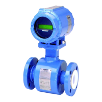
Wafer
1
/2, 1, 1
1
/2, 2, 3, 4, 6, and 8 inches
(DN 15, 25, 40, 50, 80, 100, 150, and 200)
Flanged, and Dual-Sensor Style
1
/2, 1, 1
1
/2, 2, 3, 4, 6, 8, 10 and 12 inches
(DN 15, 25, 40, 50, 80, 100, 150, 200, 250, and 300)
Pipe Schedules
Process piping Schedules 10, 40, and 80
NOTE
The appropriate bore diameter of the process piping must be entered
using the HART Communicator or AMS. Meters will be shipped from
the factory at the Schedule 40 default value unless otherwise specified.
Measurable Flow Rates
Capable of processing signals from flow applications which meet the
sizing requirements below.
To determine the appropriate flowmeter size for an application, process
conditions must be within the Reynolds number and velocity
limitations for the desired line size provided in Table A-1, Table A-2,
and Table A-3.
NOTE
Consult your local sales representative to obtain a computer sizing
program that describes in greater detail how to specify the correct
flowmeter size for an application.