Rosemount Model 8800C Vortex Flowmeter
2-14
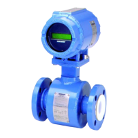
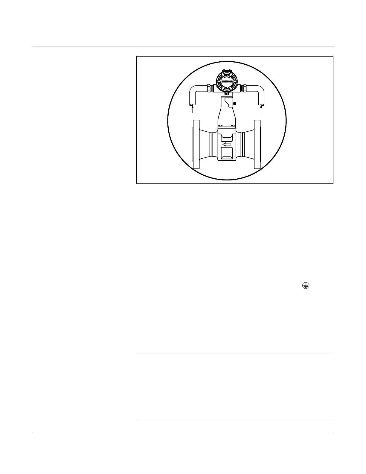
Figure 2-10. Proper Conduit Installation with Model 8800C
Cable Gland If you are using cable gland instead of conduit, follow the cable gland
manufacturer’s instructions for preparation and make the connections in a
conventional manner in accordance with local or plant electrical codes. Be
sure to properly seal unused ports to prevent moisture or other
contamination from entering the terminal block compartment of the
electronics housing.
Grounding the
Transmitter Case
The transmitter case should always be grounded in accordance with
national and local electrical codes. The most effective transmitter case
grounding method is direct connection to earth ground with minimal
impedance. Methods for grounding the transmitter case include:
• Internal Ground Connection: The Internal Ground Connection
screw is inside the FIELD TERMINALS side of the electronics
housing. This screw is identified by a ground symbol (
), and is
standard on all Model 8800C transmitters.
• External Ground Assembly: This assembly is included with the
optional transient protection terminal block (Option Code T1),
and it is included with KEMA/CENELEC Flameproof
Certification (Option Code ED), BASEEFA/CENELEC Intrinsic
Safety Certification (Option Code I1), and BASEEFA Type N
Certification (Option Code N1). The External Ground Assembly
can also be ordered with the transmitter (Option Code V5).
NOTE
Grounding the transmitter case using the threaded conduit connection
may not provide a sufficient ground. The transient protection terminal
block (Option Code T1) does not provide transient protection unless the
transmitter case is properly grounded. See Transient Protection on
page 2-36 for transient terminal block grounding. Use the above
guidelines to ground the transmitter case. Do not run the transient
protection ground wire with signal wiring as the ground wire may carry
excessive current if a lightning strike occurs.
Conduit Line
8800-000A02B
Conduit Line