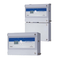
Do you have a question about the Emerson FloBoss 103 and is the answer not in the manual?
Provides a comprehensive overview of the FB100 series flow managers and their capabilities.
Details the various components and key features of the FB100 hardware.
Discusses the physical hardware components of the FB100 system, including the backplane and modules.
Outlines the primary functions and applications of the FB100 series, driven by firmware.
Explains how the FB100 measures natural gas flow using standard industry methods.
Details the general process and steps required for installing the FB100 flow managers.
Covers essential planning considerations and requirements for a successful FB100 installation.
Addresses compliance requirements for installing the FB100 in hazardous locations.
Provides guidelines and options for physically mounting the FB100 unit at the installation site.
Guides users through the initial startup sequence and basic operation of the FB100.
Explains the process of configuring the FB100 software parameters for specific applications.
Outlines the requirements and considerations for connecting power to the FB100.
Details the necessary grounding procedures for safe and reliable FB100 operation.
Covers the specifics of installing and powering the FB100 using solar energy.
Describes how to properly wire the FB100 to power, I/O, and communication devices.
Explains the crucial procedure for backing up FB100 configuration and log data.
Introduces the Input/Output capabilities and types available on the FB100 termination board.
Details the configuration and wiring for analog inputs on the FB100.
Explains how to configure and wire the analog output signals from the FB100.
Describes how to connect and wire Resistance Temperature Detector (RTD) inputs.
Provides an overview of the communication ports and methods used by the FB100.
Explains how to wire the Local Operator Interface (LOI) port for PC connectivity.
Details the EIA-232 serial communications card and its functionality.
Introduces the Dual-Variable Sensor (DVS) and its role in pressure measurement for flow calculations.
Describes how to make the physical process connections to the DVS.
Guides users on configuring the DVS through ROCLINK 800 software.
Explains the Pulse Interface Module used for rotary and turbine meter applications.
Details how to connect the pulse interface module to the process.
Covers the configuration steps for the Pulse Interface Module using ROCLINK 800.
Introduces the processes for calibrating analog inputs, RTD, and meter modules.
Provides step-by-step instructions on how to perform calibration routines for the FB100.
Explains how to adjust for zero shift in differential pressure readings after calibration.
Offers general guidelines and best practices for troubleshooting FB100 issues.
Provides specific checklists for diagnosing common problems with the FB100.
Addresses troubleshooting steps for software-related problems with the FB100.
Guides users on diagnosing and resolving power-up issues with the FB100.
Outlines essential procedures for maintenance, such as backing up data and resetting the unit.
Details the critical procedure for backing up FB100 configuration and log data.
| Manufacturer | Emerson |
|---|---|
| Model | FloBoss 103 |
| Inputs | Analog, Digital, Pulse |
| Enclosure | NEMA 4X |
| Enclosure Rating | NEMA 4X, IP66 |
| Category | Flow Computer |
| Communication Protocols | Modbus, ASCII |
| Communication Ports | RS-232, RS-485, Ethernet |
| Power Supply | 10-30 VDC |
| Operating Temperature | -40°C to 70°C (-40°F to 158°F) |
| Display | LCD display |
| Applications | Natural Gas Measurement, Liquid Measurement |
