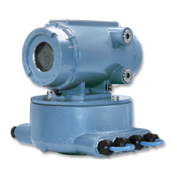
What to do if Emerson Daniel 3415 shows a System alarm?
- KKristin ClarkAug 3, 2025
To address a System alarm in Emerson Measuring Instruments, collect a Maintenance log and an audit/alarm log and then, contact your Daniel service representative.
What to do if Emerson Daniel 3415 shows a System alarm?
To address a System alarm in Emerson Measuring Instruments, collect a Maintenance log and an audit/alarm log and then, contact your Daniel service representative.
What to do if Emerson Daniel 3415 Measuring Instruments shows a Validity alarm?
To address a Validity alarm in Emerson Measuring Instruments, check Status to see a description of which validity alarms are active.
What to do if Emerson Measuring Instruments shows Chord A, Chord B, Chord C, and Chord D alarm?
If your Emerson Measuring Instruments displays Chord A, Chord B, Chord C, and Chord D alarm, inspect the meter by a service technician.
Explains the universal safety alert symbol indicating potential physical injury hazards.
Warns of serious injury or death from improper installation, operation, or maintenance.
Instructions for personnel on following manual guidelines, warnings, and notices during operation.
Lists essential equipment and information needed for meter startup procedures.
Guides on installing and configuring Daniel MeterLink for meter communication.
Details Daniel MeterLink utilities for meter configuration, testing, and reporting.
Instructions for setting up meter connection properties and creating new meter records.
Configuration for Modbus ASCII serial communication between the meter and external systems.
Explains HART communication capabilities and setup using the 4-20mA signal.
Introduces features like data log access, GC interface, and AGA10 calculation available via optional keys.
Guides on obtaining optional feature keys using the CPU board serial number.
Explains GC interface for reading gas property data from a Daniel gas chromatograph.
Details AGA10 key for calculating and comparing predicted vs. measured sound velocity.
Steps to configure optional feature keys using the Daniel MeterLink Key Manager.
Explains how meters measure transit times of ultrasonic pulses through the medium.
Details signal processing for accurate transit time using SNR, Stacking, and Filtering.
Details operational modes: Acquisition for signal acquisition and Measurement for flow velocity.
Explains averaging transit times to determine gas and sound velocity from firing paths.
Explains three volumetric flow rate values: raw, flow-condition, and base-condition.
Guides on using MeterLink to calibrate and configure meter parameters like inputs, factors, and corrections.
Explains "dry" calibration (factory set) and "wet" calibration (user-defined) steps.
Guides on calibrating analog inputs and outputs using Daniel MeterLink.
Explains calibration of flow velocity and recommends factory settings.
Guides on configuring available frequency outputs, including content and direction.
Details configuration of the single digital input (DI1) and digital output functionality.
Explains the mode for testing outputs by setting specific values.
Guides on configuring HART outputs, referring to the HART Field Device Specification Manual.
Outlines meter profile corrections for 3415 and 3416 meters, including flow profile correction.
Details configuring flow-condition pressure and temperature for meter calculations.
Guides on configuring serial port and parameters for polling a GC.
Describes five types of data logs (daily, hourly, audit, alarm, system) and how to read them.
Explains log data point actions like snapshot, average, totalize, and macro for daily and hourly logs.
Describes meter monitoring of data points for alarm limits and storing alarm log records.
Explains meter logging of system messages, storage capacity, and suppression of repetitive messages.
Details options for reading logs and their formats (Excel, CSV, Don't log to file).
Lists MeterLink Tools menu utilities for meter health, operations, baseline, upgrades, and communications.
Guides on viewing, editing, comparing, and saving meter configurations using MeterLink.
Explains viewing transducer waveforms (raw, stacked, filtered) using the MeterLink Waveform Viewer.
Describes the dialog for calculating Speed of Sound (SOS) for gas composition and conditions.
Details the utility for updating parameters like path lengths when replacing transducers or mounts.
Explains upgrading meter components using the MeterLink Tools|Program Download dialog.
Provides conversion factors for Metric and U.S. Customary units of measure.
Explains the calculation of K-Factor and Inverse K-Factor for volumetric flow rate and frequency.
Presents equations for calculating volumetric flow rate in U.S. Customary and Metric units.
Addresses common Ethernet connection issues, such as LINK LED status or communication failure.
Provides guidance for site personnel on basic mechanical and electronic troubleshooting using meters and computers.
Lists configuration parameters write-protected when the CPU Board WRITE PROT. switch is ON.
Provides tables of flow rate summary charts based on pressure and flow velocity.
States that this appendix contains engineering drawings, including the System Wiring Diagram.
| Brand | Emerson |
|---|---|
| Model | Daniel 3415 |
| Category | Measuring Instruments |
| Language | English |


