4-17
Hardware and Software Maintenance and Troubleshooting
Replacing the Sensor:
Removable and Integral
Support Tubes
The following procedure applies to flowmeters equipped with a
removable support tube, i.e. all flanged meters and ½- through 4-inch
(DN 15 through 100) wafer meters.
1. De-pressurize the flow line.
NOTE
Sensor cavity could contain line pressure if an abnormal failure has
occurred inside the meter body. De-pressurize flow line before removing
the sensor nut.
2. Remove the electronics housing (see Replacing the Electronics
Housing on page 4-13).
• For meters with a removable support tube (
1
/2- to 4-in. [15 to
100 mm] wafer meters and all flanged meters), follow steps 3-5.
Removable Support Tube (for
1
/2- to 4-in. wafer meters and all flanged
meters)
3. Loosen the four support tube anchor bolts with a
7
/16-inch open
end wrench. See Figure 4-10.
4. Remove the support tube.
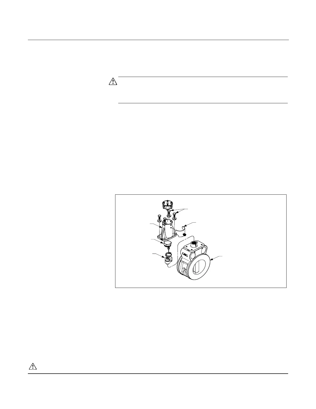
Figure 4-10. Removable Support Tube Assembly
5. Proceed to step 8.
• For meters with an integral support tube, (6- to 8-in. [100 to
200 mm] wafer meters), follow steps 6-7.
See Safety Messages on page 4-1 for complete warning information.
Removable
Support Tube
Sensor Nut
Sensor
Anchor Bolts
Meter Body
Access Cover
8800-0463A02B