2-20 / Installation & Operation CI-ControlWave EFM
Table 2-4A - RS-232 Ports (1/2/4/8) and RS-485 Ports (3/5/9) Pin Assignments
Pin
#
Signal
RS-232
Description:
RS-232 Signals
Signal
RS-485
Description:
RS-485 Signals
1 DCD Data Carrier Detect Input N/A
2 RXD Receive Data Input RXD- Receive Data - Input
3 TXD Transmit Data Output TXD- Transmit Data - Output
4 DTR Data Terminal Ready Output TXD+ Transmit Data + Output
5 GND Signal/Power Ground GND/ISOGND* Ground/Isolated Ground
6 DSR Data Set Ready Input RXD+ Receive Data + Input
7 RTS Request To Send Output N/A
8 CTS Clear To Send Input N/A
* ISOGND on Isolated RS-485 Ports Only! Note: Pin-9 not used
Table 2-4B - RS-232 Port (COM1) Connector Pin Assignments
(COM1 Connectors, i.e., Circular Local Port & D-Type ‘C1’ on CPU)
COM1
Pin #
Signal
RS-232
Description:
RS-232 Signals
Wire
Color
Local Port
RS-232 Pin #
1 DCD Data Carrier Detect Input Green 1
2 RXD Receive Data Input White 7
3 TXD Transmit Data Output Red 2
4 DTR Data Terminal Ready Output Brown 4
5 GND Power Ground Black 6
6 DSR Data Set Ready Input
7* RTS Request To Send Output
8* CTS Clear To Send Input
* = RTS connected to CTS
Control EFM
Wave
9-Pin Female
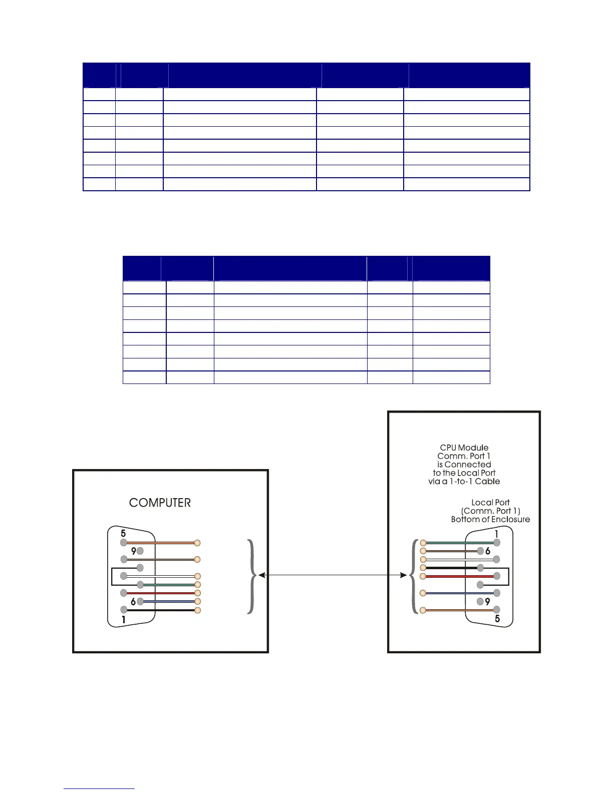
“D” Connector
(Looking into
Wire Terminal Side
of
Cable Connectors)
3 = TXD
6 = DSR
7 = RTS
8 = CTS
4 = DTR
2 = RXD
1 = DCD
5 = GND
To P2 Pin-4
To P2 Pin-2
To P2 Pin-7
To P2 Pin-3
To P2 Pin-6
To P2 Pin-5
To P2 Pin-1
9-Pin Female
“D” Connector
3 = TXD
6 = DSR
7 = RTS
8 = CTS
4 = DTR
2 = RXD
1 = DCD
5 = GND
or
vice
versa
Figure 2-13A - PC Connected to ControlWave EFM via D-Type Local Port
(Use Null Modem Cable - Bristol Part Number 392843-01-3)