13
Installation Location
Ensure the compressors are installed on a solid level base.
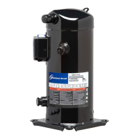
Mounting Parts
To minimize vibration and start/stop impulses, exible mounting should be used. For this purpose, one set of spring mounting parts for
each of the Stream models is delivered with each 4M* and 6M* compressor.
Due to differences in weight (cylinder/motor side), different springs have to be used on both sides. Springs have different colours for
easier identication: violet on motor side and orange on cylinder side.
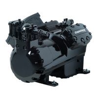
When Stream compressors are mounted in racks, rubber mounting parts should be used. A compressor may be rigidly mounted, i.e.,
without springs. In this case, more shock and vibration loading will be transmitted to the frame, so atness of mounting location is very
important. If the installation requires a very high level of vibration absorption, additional vibration absorbers - available on the market -
can be tted between the rails and the foundation.
Figure 6
Transport position
Transport clamp
Operational position
44
2
TWIN compressors are tted to U mounting rails using rubber pads.
Rubber mounting parts can be delivered as a variation instead of the spring mounting parts, or as a separate kit.
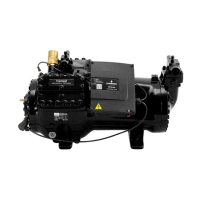
Unevenness in the mounting surface will have to be taken by the rack and/or the compressor bottom plate/feet. Excessive unevenness
can result in too high mechanical stress to the system and could damage the compressor or rack. Therefore, the atness of the mounting
location is essential. In addition, both vibration/shock and mechanical stress to compressor can be avoided by using rubber mounting
parts.
NOTE: For rigid mounting on rack with rubber mounting parts, the nuts should be tightened to the rubber surface without
rubber deformation to keep efficient operation of the rubber. The maximum applicable torque without rubber deformation is
50Nm.
Rubber pads
Spacer
Figure 7

 Loading...