6 7
Capacity Control
For 4M* and 6M* compressors, a mechanical capacity control is available. The system used is blocked suction. Be aware that unloaded
operation changes the application range of the compressor.
NOTE: For the application range of the compressors with capacity control, refer to Technical Information D7.21.2
“Stream semi-hermetic compressor capacity control”.
Oil Pumps
The oil pumps used for Stream compressors are independent of their rotating direction. Stream compressors are delivered with
CoreSense
™
Diagnostics. The oil pump integrates the electronic switch for integrating oil pressure safety functionality.
Oil Pressure
Normal oil pressure is between 1.05 and 4.2 bar higher than crankcase pressure. Net oil pressure can be read by connecting two pressure
gauges to the compressor and comparing the readings. One gauge should be connected to the oil pump. The second gauge should be
connected to the crankcase (T-tting instead of plug on the compressor crankcase) or the suction service valve.
During irregular operating condition, e.g., a blockage of the suction lter, the pressure measured at the suction shut-off valve of the
compressor may differ widely from that measured at the crankcase. Therefore, pressure drops have to be avoided.
Compressor Cooling
Compressor motors must always be cooled, while cylinder head cooling may also be needed at certain operating conditions.
All Stream compressors are suction gas-cooled. With suction gas-cooled compressors, the motor is cooled by refrigerant gas that is
led over the motor. An additional fan (70W vertical air ow fan) may be required depending upon the operation conditions. Please see
Operating Envelopes.
Demand Cooling
“Demand Cooling”, as the term implies, means liquid refrigerant injection on demand. If a low-temperature R22 or R407F installation is
needed, the following compressors can be equipped with demand cooling. Models without demand cooling are also available from Asia.
Please contact the representative sales manager in your region for more information.
For Demand Cooling installation, refer to the installation manual in accessory kit. Please see Operating Envelopes.
Unloaded Start
With direct starting, the motor of a compressor is switched directly into the mains by means of a switch. The resulting breakaway
starting current amounts to multiple times the rated motor current operating maximum, without consideration being given to transient
phenomena. In the case of high-powered motors, the breakaway starting currents become so large that they lead to disruptive voltage
dips in the mains. Compressors that are subject to current limitation must, therefore, by all means, be equipped with starting load
reduction to guarantee perfect starting even when the voltages amount to less than approximately 85% of the voltage on the nameplate.
4MF-13 4ML-15 4MM-20 4MT-22 4MU-25
6MM-30 6MT-35 6MU-40
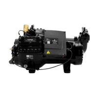
Design Features
Compressor Structure
Each cylinder head has 2 plugged 1/8” - 27NPTF tapped holes for
connecting high-pressure switches.
These high-pressure switches must be calibrated and tested before
putting the compressor into service. They must stop the compressor if
the allowable pressure has exceeded.
The complete cylinder head is under discharge pressure.
Figure 1
All compressors are tted with Stream valve plates which cannot be dismantled. To maintain the high capacity of these compressors the
correct valve-plate-to-body gasket must always be selected in case of exchange.

 Loading...