EasyManua.ls Logo

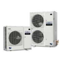
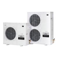
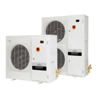
Emerson Copeland Scroll XFAM-030Z-TFC User Manual

Emerson Copeland Scroll XFAM-030Z-TFC
35 pages
To Next Page IconTo Next Page
Page #1 background imageLoading...
Page #1 background image
Copeland Scroll
Outdoor Refrigeration Unit
Installation and reference manual
Models:
XFAL, XFAM, XFAP
1.5 to 6 HP

Table of Contents

Question and Answer IconNeed help?

Do you have a question about the Emerson Copeland Scroll XFAM-030Z-TFC and is the answer not in the manual?

Emerson Copeland Scroll XFAM-030Z-TFC Specifications

General IconGeneral
BrandEmerson
ModelCopeland Scroll XFAM-030Z-TFC
CategoryHeat Pump
LanguageEnglish

Summary

Safety Instructions

General Safety Warnings

3. Electrical/Physical Data

4. Installation/Piping Instructions

5. Quick Setup Guide

6. User Interface

6.10. Alarm Menu

6.11. HOT-KEY Controller Upload

6.12. HOT-KEY Controller Download

Condensing Unit Operational Control

6.18. Suction Pressure Control

6.19. Fan Control

6.20. Defrost Controls

6.21. Enhanced Vapor Injection (EVI) for Low Temperature Units

6.21.1. Low Temp EVI DLT Protection Error Handling

6.22. Medium Temperature DLT Protection

6.23. Over-Current Protection

6.24. Incorrect Phase Sequence Protection

6.25. Loss of Phase Protection - Current

6.26. Open Run Circuit (Single Phase Only)

6.27. Open Start Circuit (Single Phase Only)

6.28. Over/Under Voltage Protection

6.29. Phase Imbalance (3 Phase Only)

6.30. Compressor Internal Thermal Protection

6.31. Fixed High Pressure Control

7. Local and Remote Displays and Communication

8. Physical and Installation Requirements

High Voltage Connections

Sensor Connections

9. Wiring Diagrams

Low Temp 1-Phase 2.0-3.5 HP Wiring

Wiring diagram for specific low-temperature, single-phase models.

Low Temp 1-Phase 4-5 HP Wiring

Wiring diagram for specific low-temperature, single-phase models.

Medium Temp 1-Phase 1.5-3 HP Wiring

Wiring diagram for specific medium-temperature, single-phase models.

Medium Temp 3-Phase 4.5-6 HP Wiring

Wiring diagram for specific medium-temperature, three-phase models.

Low Temp 3-Phase 2-3 HP Wiring

Wiring diagram for specific low-temperature, three-phase models.

Low Temp 3-Phase 4-6 HP Wiring

Wiring diagram for specific low-temperature, three-phase models.

Medium Temp 3-Phase 1.5-3 HP Wiring

Wiring diagram for specific medium-temperature, three-phase models.

10. Refrigerant Liquid Temperature Valve Capacity Multiplier Correction Factors

11. Alarm Codes

Alarm Code Details

Detailed explanation of alarm codes, their levels, diagnostics, and possible fixes.

12. Sensor Values

13. Parameters

Compressor Safety Parameters

Safety settings for compressor operation, delays, and trip counts.

Related product manuals