EasyManua.ls Logo

Emerson Copeland Scroll XFAM-060Z-TFC User Manual

Emerson Copeland Scroll XFAM-060Z-TFC
35 pages
To Next Page IconTo Next Page
Page #1 background imageLoading...
Page #1 background image
Copeland Scroll
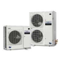
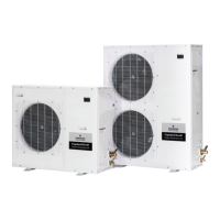
Outdoor Refrigeration Unit
Installation and reference manual
Models:
XFAL, XFAM, XFAP
1.5 to 6 HP

Table of Contents

Question and Answer IconNeed help?

Do you have a question about the Emerson Copeland Scroll XFAM-060Z-TFC and is the answer not in the manual?

Emerson Copeland Scroll XFAM-060Z-TFC Specifications

General IconGeneral
ModelXFAM-060Z-TFC
CategoryHeat Pump
Compressor TypeScroll
BrandEmerson Copeland
RefrigerantR-410A
Voltage (VAC)208-230
Phase1
Frequency (Hz)60
Suction Line Size (in)1 1/8
Capacity5 tons
Cooling Capacity (BTU/h)60000

Summary

Safety Instructions

Safety Icon Explanation

Explanation of safety icons: DANGER, WARNING, CAUTION, and NOTICE.

Instructions Pertaining to Risk of Electrical Shock, Fire, or Injury to Persons

Hazard Warnings

Details electrical, pressurized system, burn, and compressor handling hazards.

Safety Statements

Lists general safety statements for installation and maintenance.

5. Quick Setup Guide

6.10. Alarm Menu

Accessing and Reviewing Alarms

Procedure to enter the alarm menu, list alarms, and view time details.

6.11. How to Program a HOT-KEY From the Controller (UPLOAD TO OVERWRITE HOT-KEY)

6.12. How to Program a Controller Using a HOT-KEY (Download)

6.20. Defrost Controls

6.21. Enhanced Vapor Injection (EVI) for Low Temperature Units

EVI System Operation and Control

Explanation of the EVI system and its PI control algorithm.

6.21.1. Low Temp EVI Discharge Line Temperature Protection Mode

DLT Protection and Sensor Failure Handling

How the DLT protection mode and sensor failures are managed.

6.21.2. EVI System Checks (XFAL units only)

6.21.3. Constant Liquid Temperature Mode For Low Ambient EVI Injection

6.22. Medium Temperature DLT Protection

DLT Protection and Overheat Prevention

How liquid injection prevents compressor overheat.

6.22.1. Medium Temperature DLT Protection Error Handling

DLT Sensor Failure Management

How DLT sensor failures are handled and injection is managed.

6.23. Over-Current Protection

Over-Current Faults and Lockout

How over-current conditions are detected and handled.

6.24. Incorrect Phase Sequence Protection (3 Phase Only)

Phase Sequence Error Detection

How incorrect phase sequence is detected and managed.

6.25. Loss of Phase Protection - Current (3 Phase Only)

Loss of Phase Detection and Lockout

How loss of phase is detected and the resulting lockout.

6.26. Open Run Circuit (Single Phase Only)

Open Run Circuit Detection

How an open run circuit is detected and handled.

6.27. Open Start Circuit (Single Phase Only)

Open Start Circuit Detection

How an open start circuit is detected and handled.

6.28. Over/Under Voltage Protection

Voltage Fluctuation Protection

How over/under voltage conditions trigger shutdown and lockout.

6.29. Phase Imbalance (3 Phase Only)

Phase Imbalance Detection

How phase imbalance is detected and managed.

6.30. Compressor Internal Thermal Protection

Compressor Thermal Protector Issues

How internal thermal protector trips are detected.

6.31. Fixed High Pressure Control

High Pressure Switch Operation

How the fixed high pressure control functions and triggers shutdowns.

6.33. Anti-Flood Back Warning

6.34. High Condensing Temperature Warning

Low Temp 1-Phase 2.0-3.5 HP 1 Condenser Fan Wiring Diagram

Controller Terminal Connections

Low Temp 1-Phase 4-5 HP 2 Condenser Fans Wiring Diagram

Medium Temp 1-Phase 1.5-3 HP 1 Condenser Fan Wiring Diagram

Medium Temp 3-Phase 4.5-6 HP 2 Condenser Fans Wiring Diagram

Low Temp 3-Phase 2-3 HP 1 Condenser Fans Wiring Diagram

Low Temp 3-Phase 4-6 HP 2 Condenser Fans Wiring Diagram

Medium Temp 3-Phase 1.5-3 HP 1 Condenser Fan Wiring Diagram

Medium Temp 1-Phase 4.5-5 HP 2 Condenser Fans Wiring Diagram

11. Alarm Codes

Alarm Code Descriptions and Resolutions

List of alarm codes, their descriptions, diagnostic resolutions, and possible fixes.

13. Parameters

Parameters (continued)

Related product manuals