12 C6.2.27/0716-0219/E
5 Electrical connection
5.1 General recommendations
The compressor terminal box has a wiring diagram on the inside of its cover. Before connecting
the compressor, ensure the supply voltage, the phases and the frequency match the nameplate
data.
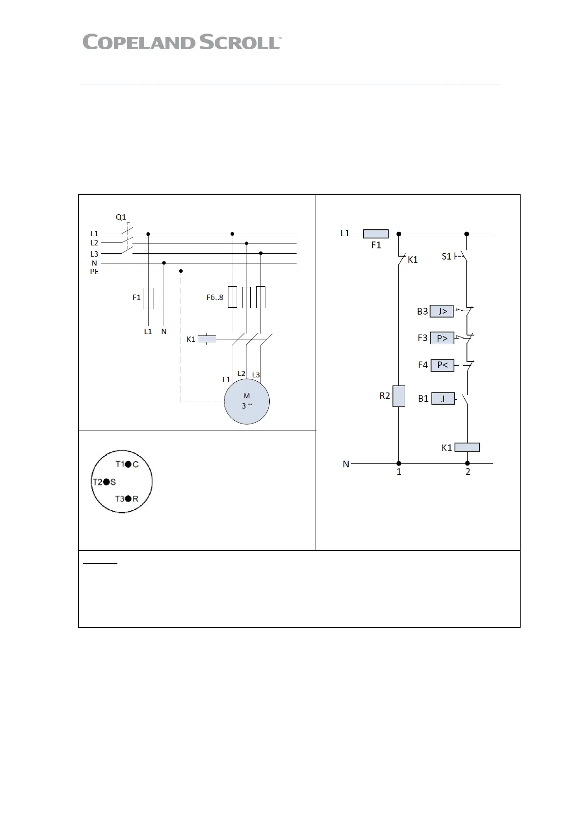
5.2 Electrical installation
Three-phase compressors (TF*) with internal motor protection:
Power circuit Control circuit
Motor terminal connections
Three-phase compressors are connected to
the T1, T2 and T3 connections
Legend
B1 ....... Room thermostat K1 ........ Contactor
B3 ....... Discharge gas thermostat R2 ........ Crankcase heater
F1 ....... Fuse S1 ........ Auxiliary switch
F3 ....... HP switch
F4 ....... LP switch
Figure 9

 Loading...