13
15°
45°
D 3.453 3.453 3.453 3.453 3.453 3.675 3.675 3.675 4.796
E 3.453 3.453 3.453 3.453 3.453 3.675 3.675 3.675 4.796
F 4.013 4.013 4.013 4.013 4.013 4.013 4.013 4.013 4.633
G 3.763 3.763 3.763 3.763 3.763 3.763 3.763 4.763 4.763
H 3.889 3.889 3.889 3.889 4.826 4.826 4.826 4.826 -
2J3 4.326 4.326 - - - - - - -
2½J4 - - 4.357 4.357 5.107 5.107 - - -
3J4 - - 6.232 6.232 6.232 6.232 6.441 6.441 -
K 4.701 4.701 4.701 4.701 5.826 5.826 7.013 7.013 -
L 5.045 5.045 5.263 5.263 5.263 6.236 6.236 6.236 -
M 5.576 5.576 5.576 5.576 5.576 6.389 6.389 - -
N 6.117 6.117 6.117 6.117 6.117 - - - -
P 5.857 5.857 7.607 7.607 7.607 - - - -
Q 7.732 7.732 7.732 7.732 7.732 - - - -
R 8.117 8.117 8.117 8.117 8.117 - - - -
T, T2 9.576 9.576 9.576 - *9.576 - - - -
'A'
0.332 0.370 0.369 0.398 0.429 0.531 0.546 0.605 0.632 0.692 0.783 0.781 0.839
'B'
0.021 0.025 0.030 0.036 0.044 0.051 0.063 0.070 0.076 0.091 0.118 0.139 0.176
0.023 0.027 0.032 0.038 0.046 0.053 0.065 0.072 0.078 0.093 0.120 0.141 0.178
CROSBY STYLE JOS-E, JBS-E, JLT*-JBS-E, JLT*-JOS-E VALVES
InstallatIon and MaIntenance InstructIons
6.5.2
Machining of nozzle seats
If machining of the nozzle seat or
other major repairs are necessary, it is
recommended that the valve be returned
to a Emerson facility for repair. All
parts must be machined accurately per
Emerson specifications.
No pressure relief valve will be tight,
nor will it operate properly unless all
parts are machined correctly. The most
satisfactory way to machine a nozzle is to
remove it from the valve body. However,
it may also be machined while assembled
within the valve body. In any event, it is
vitally important that the seating surfaces
run absolutely true before machining.
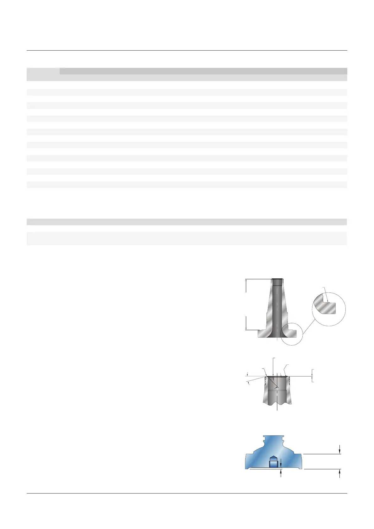
FIGURE 10
Nozzle seat critical dimensions
Minimum
face to
seat dim,
refer to
Table 8
Raised seal face
Related
surfaces
Seat
0.010-0.014
machined
0.008 min after
lapping
0.004 after lapping
* Type 42, 44 not available
6.5.3 Machining of disc insert seats
When the damage to the disc insert seat
is too severe to be removed by lapping,
the disc insert may be machined and
lapped provided that minimum seat height
is maintained (Figure 11 and Table 9).
FIGURE 11
Disc insert minimum seat height (Table 9)
'B' mach.
'A' min.
after lapping
TABLE 9 - Disc insert minimum seat heights
Orifice
D and E
F G H J K L M N P Q R T
TABLE 8 - Minimum nozzle face to seat dimensions (see Figure 10)
Valve type
Orifice 12, 14, 15, 16 22, 24, 25, 26 32, 34, 35, 36, 37 47 42, 44, 45, 46 57 55, 56 64, 65, 66, 67 75, 76, 77
Machining dimensions for Crosby Style
JOS-E/JBS-E valves with metal-to-metal
nozzle seats are shown in Figure 10
and Table 8. Remove only enough metal
to restore the surface to its original
condition. Turning to the smoothest
possible finish will facilitate lapping.
The nozzle must be replaced when
minimum face to seat dimension is
reached. This critical dimension is shown
in Table 8.
 Loading...