14
CROSBY STYLE JOS-E, JBS-E, JLT*-JBS-E, JLT*-JOS-E VALVES
InstallatIon and MaIntenance InstructIons
6.6 Assembly
All components should be clean. Before
assembling the following parts, lubricate with
pure nickel 'Never-Seez'.
• Nozzle and body threads
• Nozzle and body sealing surface
• All studs and nut threads
• Spindle and threads
• Set screw threads
• Spring washer bevels
• Adjusting bolt and bonnet threads
• Bonnet pipe plug
• Cap threads
• All metal gaskets
• Dog shaft bearing threads
• Disc holder threads (bellows valves only)
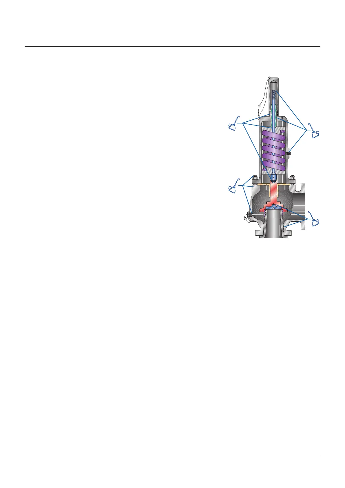
FIGURE 12
Recommended lubrication points
Lubricate the spindle point thrust bearing and
disc insert bearing with pure nickel 'Never-
Seez'. Special attention should be given to
the guiding surfaces, bearing surfaces and
gasket surfaces to ensure that they are clean,
undamaged and ready for assembly (Figure 12).
For parts identification, refer to Figure 1.
6.6.1 Before installing the nozzle (2) apply
lubricant to the flange surface in contact
with the valve body (1) and on the body
to nozzle threads. Screw the nozzle (2)
into the valve body (1) and tighten with a
nozzle wrench.
6.6.2
Screw the nozzle ring (3) onto the nozzle (2).
Note: the top of the nozzle ring should be
above the nozzle seating surface. For P,
Q, R and T orifice Style JLT, position the
nozzle ring per Table 2.
6.6.3 For bellows valves only, place the disc
holder in a vise (larger sizes may require
a 3 jaw vise) as shown in Figure 8.
Installthe tailpiece gasket (29).
Screw the bellows assembly onto the
disc holder. Tighten with a suitable
wrench.
6.6.4 Assemble the disc insert (8) and the disc
holder (5).
(See Figure 14 for O-ring soft
seat assembly).
Install the disc insert retention clip (9)
onto the disc insert.
Install the disc insert into the disc
holder. The disc insert should snap into
place using handforce only.
Safety precautions should be followed
whenever heavy parts are being lifted or
transported.
Dropping the disc holder assembly may
dislodge the insert.
6.6.5
Assemble the disc holder (5) and guide (15)
by sliding the guide over the disc holder.
Note: the guide for D and E orifice valves
protrudes up into the valve bonnet.
6.6.6 Install the two guide gaskets (28),
oneabove and one below the guide.
Note: when assembling bellows valves,
the bellows flange eliminates the need
for a bottom guide gasket.
6.6.7
While holding the top of the disc holder,
install the guide into the body. Align the
hole of the guide with the body outlet. Once
the guide is seated, the disc holder and
disc insert can be lowered onto the nozzle.
Note: lower the nozzle ring below the
seats so that it moves freely.
6.6.8 Place the spring (18) and washers (19)
onto the spindle (16) and assemble the
spindle to the disc holder (5) with the
spindle cotter pins.
Note: no cotter pins are required in D
through K orifice sizes; all other orifice
sizes use two cotter pins.
6.6.9
Lower the bonnet (20) over the spindle
and spring assembly onto the bonnet
studs (21) in the body. Position the bonnet
counter bore on the O.D. of the guide and
lower the bonnet onto the guide.
6.6.10 Screw the bonnet nuts (22) onto the
bonnet studs and tighten down evenly to
prevent unnecessary strain and possible
misalignment.
6.6.11 Screw the adjusting bolt (24) and nut (25)
into the top of the bonnet to apply force
on the spring. (The original set pressure
can be approximated by screwing the
adjusting bolt down to the predetermined
measurement).
6.6.12 Move the nozzle ring up until it touches
the disc holder, then lower it two
notches. This is a test stand setting only.
6.6.13 Place the set screw gasket (27) onto the
set screw (4) and screw the set screw
into the body engaging the nozzle ring.
The nozzle ring should move back and
forth slightly after the set screw is
tightened.
6.6.14 The valve is now ready for testing.
After testing, the following measures
should be taken:
• Be sure that adjusting bolt nut (25) is
locked.
• Return the nozzle ring to either the
original recorded position or to the
recommended position shown in Table 1.
• Install the cap or lifting device.
SeeFigure 14 for lifting lever assembly.
• Seal the cap or lifting lever device
and nozzle ring set screw to prevent
tampering.
 Loading...