15
6.7 Restricted lift valves
Crosby JOS-E and JLT-JOS- E pressure relief
valves are available in a restricted lift version.
All J series variations including JBS and all
service medias may be supplied in a restricted
lift version. The purpose of a restricted lift valve
is to more closely match the required capacity
of the protected vessel or pipe with the actual
and rated capacities of the relief valve providing
over-pressure protection.
Restricted lift (RL) versions of the J series may
be built by a certified Emerson manufacturing
facility or by an ASME certified Assembler with
the required certification specific to the RL
version (National Board certificates 01045 and
01382). Any ASME marked RL valve may be VR
repaired by a repair organization certified under
the National Board VR repair program. Existing
non- restricted lift versions of the J series may
be converted to the restricted lift version by
VR certificate holders. In addition existing RL
versions may have their lift modified using the
same procedures.
NOTE
Restricted lift valves may be identified by the restricted
lift nameplate by model number with “-RL".
6.7.1
Restricted lift valves have a limit spacer
that prevents the disc and disc holder
from lifting its limits. These valves may be
restricted to a minimum lift of 30% of the
full rated capacity or .080˝ (2.03 mm).It is
important to check lift on all restricted lift
valves to ensure accuracy of the capacity
on the nameplate. For production
purposes the spacers are precut for 10%
increments. 5% increments can be added
for K orifice and larger.
6.7.2 Determining the correct limit spacer height
• T
he nameplate capacity should
be as specified on the nameplate
or determined by calculation
(See example on page 18).
• The required lift should also
be specified on the nameplate
or determined by calculation
(See example on page 18).
• Select the limit spacer(s) to the
required limit spacer height
(See Table 10 and 11).
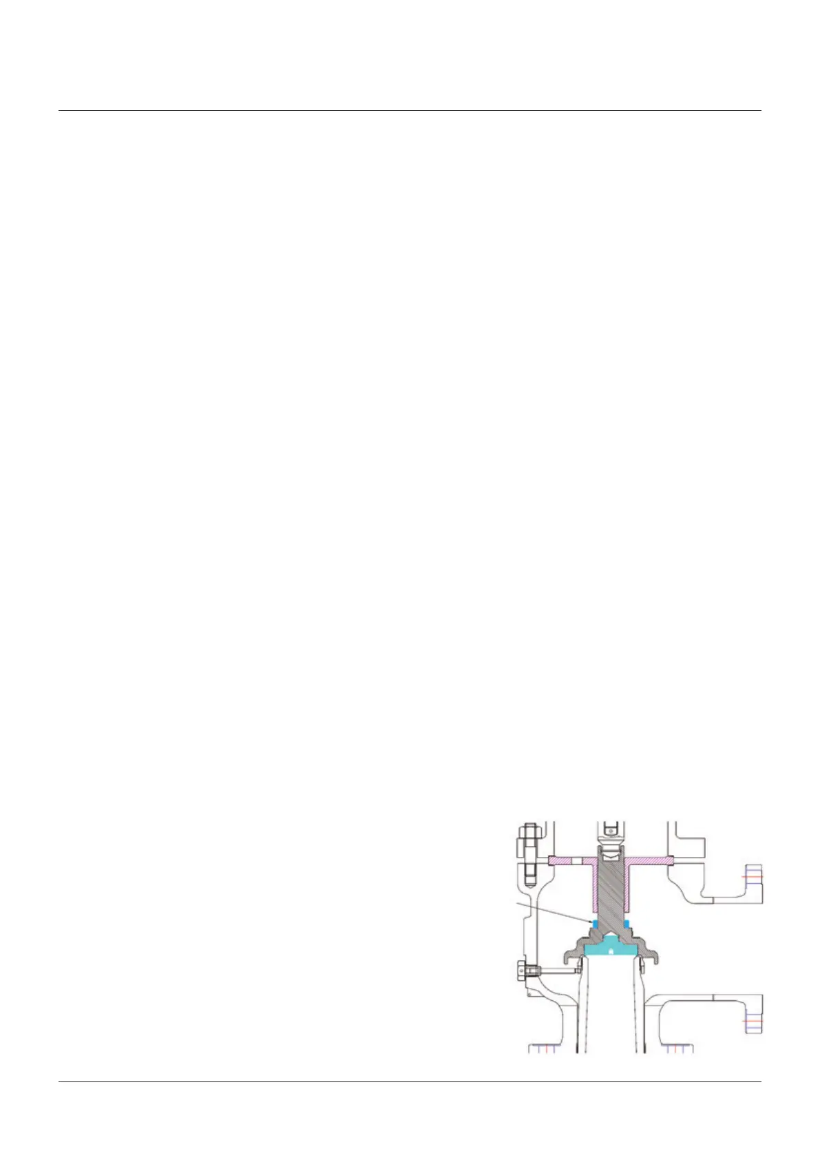
6.7.3 Measure the valve lift.
• Install the limit spacer (see Figure 13)
with the chamfer down and reassemble
the valve as described in Steps 6.6.1
through 6.6.10.
Note: install bellows to disc holder for
JBS F orifice valve, then install spacer.
•
Measure the lift of the valve and
compare it with the required lift as given
on the restricted lift nameplate with
tolerance (.020”, +0.020” [-0.50 mm,
+0.50 mm]).
• Based on the results, if the lift is not in
the tolera
nce:
If the actual lift is less than required, machine
the limit spacer as necessary to obtain the
required lift. (Machine chamfer, deburr and
polish before installation into the valve.)
If the actual lift is greater than required, obtain
a new next taller limit spacer, and return to
section 13.3.1. (Machine chamfer, deburr and
polish before installation into valve.)
• Once correct lift is obtained,
disassemble the valve.
•
Ensure the limit spacer has been
chamfered to fit over the radius of the
disc holder. The limit spacer must be
installed so that the chamfered end is
mating to the back face of disc holder,
and not sitting on the disc holder radius.
• Prior assembly, verify the lift for each
valve.
FIGURE 13
Restricted lift spacer
CAUTION
Do not interchange internal parts or use a
different nozzle after a set of parts has been
custom-fit.
6.7.4 Assembly
Valves need to be assembled as per
section 6.6.
6.7.5 Restricted Lift Nameplate
For new restricted lift version valves, use
the restricted lift nameplate (See Figure 2.)
I
f a non-restricted lift J series PRV is
converted to the RL version, or if the
restricted lift is changed on an existing
RL version valve the following procedure
regarding nameplates should be followed.
• The information on the original ASME
nameplate which is changed by the
conversion, such as model number,
capacity and restricted lift should be
lightly etched out.
• Information changed by conversion of
the valve or change to the restricted
lift shall be included on the repair
nameplate to serve as a record of
the conversion and its effect on the
performance of the PRV.
CROSBY STYLE JOS-E, JBS-E, JLT*-JBS-E, JLT*-JOS-E VALVES
InstallatIon and MaIntenance InstructIons
Lift
restricting
spacer
 Loading...