Page/Seite 38
Product Information / Produktinformation
A6151
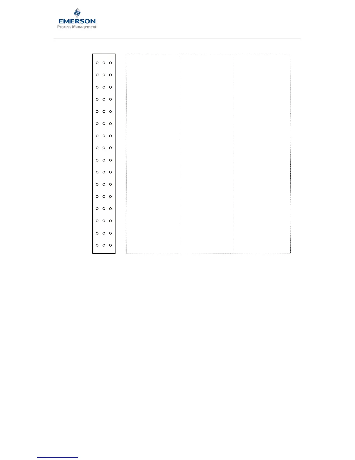
Connection Diagrams and Figures / Anschlusspläne und Abbildungen
2
6
4
8
10
12
14
16
18
20
22
24
26
28
30
32
2
6
4
8
10
12
14
16
18
20
22
24
26
28
30
32
db z
d
b
UB+ (+24V)
U
−
(0V/Common)
UN+ (+24V, redundant)
Supply2+ (sensor)
Supply1− (sensor)
Supply1+ (sensor)
AIN2− (input)
Supply2− (sensor)
AIN1− (input)
AIN2+ (input)
C Screen / Common
AIN1+ (input)
A (RS485) Common
B (RS485)
NGL2 (scaled dc output) GND Common
NGL1 (scaled dc output)
EO1 (voltage output1)
EI1 (voltage input1)
AC1 (sensor raw signal)*
EO2 (voltage output2) EL2 (voltage input2)
AC2 (sensor raw signal)*
GWM (limit value) I1−(current output common)
I1+ (current output CH1)
NC I2−(current output common)
I2+ (current output CH2)
KEY (N) (key signal input)
GND ES (external lock)
SC−A (oper. principle alert)
GND
SC−D (oper.principle danger)
D1−C (danger1 collector)
D2−C (danger2 collector)
A1−C (alert collector)
A2−C (alert2 collector)
C1−C (chan. clear1 collector)
C2−C (chan.clear2 collector)
D1−E (danger1 emitter)
D2−E (danger2 emitter)
A1−E (alert1 emitter)
A2−E (alert2 emitter)
C1−E (chan.clear1 emitter)
C2−E (chan.clear2 emitter)
z
*Only if Jumper J2 is closed. / Nur wenn Jumper J2 gesetzt ist.
Pin allocation / Steckerbelegung
 Loading...