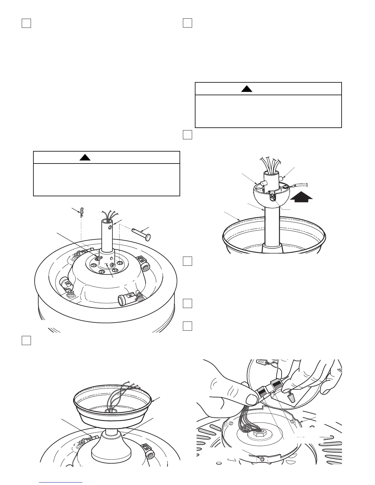
4. Reinstall the hanger ball (Figure 5) on the downrod
as follows. Route the four 80” motor leads through
the hanger ball. Position the pin through the two
holes in the downrod and align the hanger ball so
the pin is captured in the groove in the top of the
hanger ball. Pull the hanger ball up tight against
the pin and securely tighten the setscrew in the
hanger ball. A loose setscrew could create fan
wobble.
5.Screw the four 25-watt candelabra bulbs into the
uplight sockets on top of the fan motor
assembly (Figure 4).
6.The fan comes with blue, black, orange and white
leads that are 80” long. Before installing fan,
measure up approximately 6 to 9-inches above top
of hanger ball/downrod assembly. Cut off excess
leads and strip back insulation 1/2-inch from end of
leads.
7. Turn the fan assembly upside down in preparation
for mounting the switch housing assembly and fan
blades.
8. Engage the connector of the switch housing
assembly with the motor connector (Figure 6). The
two connectors are keyed and color-coded and
must be mated correctly (color-to-color) before
they can be engaged. Make sure the connector
latch closes properly.
2. Separate, untwist and unkink the four 80” motor
leads. Route the motor lead wires through the
downrod. Remove the setscrews from the motor
coupling. Align the clevis pin holes in the downrod
with the holes in the motor coupling. Install the cle-
vis pin and secure with the hairpin clip (Figure 3).
The clevis pin must go through the holes in the
motor coupling and the holes in the downrod. Be
sure to push the straight leg of the hairpin clip
through the hole near the end of the clevis pin until
the curved portion of the hairpin clip snaps around
the clevis pin. The hairpin clip must be properly
installed to prevent the clevis pin from working
loose. Pull on the downrod to make sure the clevis
pin is properly installed. Reinstall the setscrews in
the motor coupling. Check that the setscrews are
tightened securely (Figure 3).
NOTE: The setscrew must be properly installed as
described above, or fan wobble could result.
3. Make sure the grommet is properly installed in the
coupling cover, then slide the coupling cover on the
downrod until it rests on the motor housing. Place
the ceiling cover over the downrod. Be sure that
the ceiling cover and the coupling cover are both
oriented correctly (Figure 4).
5
It is critical that the clevis pin in the motor coupling
is properly installed and the setscrew securely
tightened. Failure to verify that the pin and setscrew
are properly installed could result in the fan falling.
WARNING
!
 Loading...