Operating instruction
EC3-D7x Digital Superheat Controller
EC3-D72 with TCP/IP communication capability
Emerson Climate Technologies GmbH www.emersonclimate.eu
Am Borsigturm 31 I 13507 Berlin I Germany Date: 18.07.2017 EC3-D7x_OI_ML_R06_865019.docx
Preparation for Start-up:
• Vacuum the entire refrigeration system.
• Note: EMERSON Electrical Control Valves EX4-6 are delivered at half open
position. Do not charge system before closure of valve.
• Apply supply voltage 24 V to EC3 while the digital input is 0 V (open). The valve
will be driven to close position.
• After closure of valve, start to charge the system with refrigerant.
• Start the system and check the superheat and operating conditions.
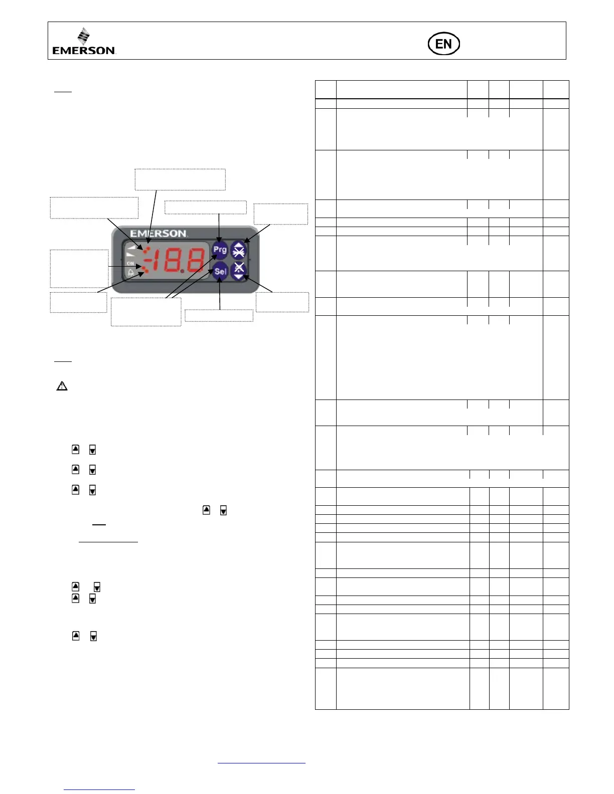
ECD-002 display/keypad unit: (LEDs and button functions)
Procedure for parameter modification using ECD-002:
• Note: Some of the functions/parameters (manual control and TCP/IP
configuration) cannot be modified when using ECD-002 comparing to a set-up by
PC via TCP/IP.
• Warning:
All alarms are disabled during manual control. We do not recommend
unattended operation of system during manual control.
• The parameters can be accessed via the 4-button keypad. The configuration
parameters are protected by a numerical password. The default password is “12”.
To select the parameter configuration:
• Press the PRG button for more than 5 seconds, a flashing “0” is displayed
• Press or until “12” is displayed (password)
• Press SEL to confirm password
• Press or to show the code of the parameter that must be changed;
• Press SEL to display the selected parameter value;
• Press or to increase or decrease the value;
• Press SEL to temporarily confirm the new value and display its code;
• Repeat the procedure from the beginning "press or to show..."
• To exit and save the new settings: Press PRG to confirm the new values and exit
the parameters modification procedure.
• To exit without modifying any parameters: Do not press any button for at least
60 seconds (TIME OUT).
Special Functions:
The Special Functions can be activated by:
• Press and together for more than 5 seconds, a flashing “0” is displayed.
• Press or until the password is displayed (default = “12”).
If password was changed, select the new password.
• Press SEL to confirm password
A “0” is displayed and the Special Function mode is activated.
• Press or to select the function. The number of special functions is dynamic
and controller dependent. See list below.
0: Reset controller to factory settings (this action is possible only when
digital input is 0 V i.e. open).
1: Displays the current TCP/IP address.
2: Assign temporary 192.168.1.101 as TCP/IP address if EC3-D72x has
different address.
• Press SEL to activate the function without leaving the special function mode.
• Press PRG to activate the function and leave the special function mode.
Main parameters:
(must be checked and modified if necessary)
Code
Parameter description and choices Min Max
0 = R22 1 = R134a 2 = R507 3 = R404A 4 = R407C
5 = R410A 6 = R124 7 = R744 (subcritical application)
8 = R407A 9 = R407F 10 = R32* 11 = R448A
12 = R449A 13 = R450A 14 = R513A 15 = R1234ze
Installed pressure sensor type
0 = PT5-07x (for R22 / R134a / R507 / R404A / R407A / R407C /
R407F / R124 / R448A /R449A / R450A / R513A /
R1234ze)
1 = PT5-18x (for R410A/ R32)
2 = PT5-30x (for R410A / R744 / R32)
Start opening duration (second)
Low superheat alarm function
0 = disable (for flooded evaporator)
1 = enable auto reset 2 = enable manual reset
Cut-out at 0.5K (if it maintains 1 min.); Cut-in immediately at 3K
If uL enabled (auto or manual)
MOP set-point (°C) saturation temperature
**) Factory setting is according to selected refrigerant (u0):
+13°C - R22 +15°C - R134a +7°C - R507
+7°C - R404A +15°C - R407C +15°C - R410A
+50°C - R124 -5°C - R744 +10°C - R407A
+10°C - R407F +10°C - R32 +12°C - R448A
+12°C - R449A +19°C - R450A +13°C - R513A
+24°C - R1234ze
*) Min. and Max. setting values are dependent to selected type of
0 = °C, K, bar 1 = °F, R, psig
(Psig values are divided by 10. Example: Display 12.5 is 125 psig)
0 = Measured superheat (K) 1 = Measured evaporating pressure, (bar);
2 = Valve opening (%) 3 = Measured coil-out temperature (°C)
4 = Calculated evaporating temperature (°C) from the pressure
5 = Compressor capacity in %
High superheat alarm function
0 = disable, 1 = enable auto reset
High superheat alarm setpoint
High superheat alarm delay, min.
Freeze protection cut-out, °C
Freeze protection cut-in, °C
Freeze protection alarm function
0 = disable, 1 = enable auto-reset,
Freeze protection alarm delay, sec.
Pump-down function
(0 = disable, 1 = enable auto-reset)
Pump-down time delay, sec.
Low pressure alarm function
(0 = disable, 1 = enable auto-reset,
Low pressure alarm cut-out, barg
Low pressure alarm delay, sec.
Low pressure alarm cut-in, barg
0: Alarm = normal, pump down. = normal
1: Alarm = inverse, pump down. = normal
2: Alarm = normal, pump down. = inverse
3: Alarm = inverse, pump down. = inverse
Blinking: valve is closing
Blinking: valve is opening
OFF: no demand
Blinking: pump
down
Parameters setting/saving
Next parameter/
value (higher)
Next parameter/
value (lower)

 Loading...


