Operating instruction
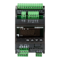
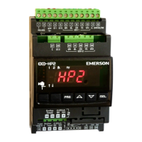
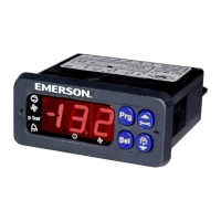
EXD-HP1/2 Controller with ModBus
communication capability
Emerson Climate Technologies GmbH www.emersonclimate.eu
Am Borsigturm 31 I 13507 Berlin I Germany Date: 08.09.2017 EXD-HP12_OI_ML_R03_865921.docx
Manual alarm reset/clearing functional alarms (except hardware errors):
Press and together for 5 seconds. When the clearing is done, “CL”
message appears for 2 seconds.
Manual mode operation
Press and together for 5 seconds to access to manual mode operation.
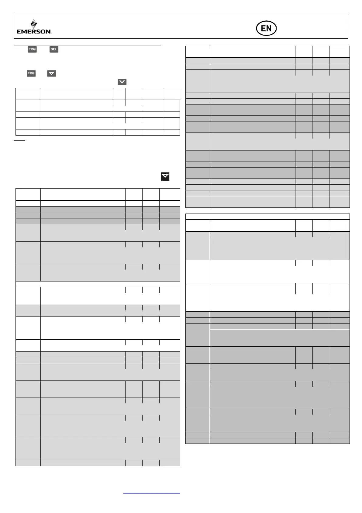
List of parameters in scrolling sequence by pressing button
Code
Parameter description and choices
Min Max
Manual mode operation; circuit 1
Manual mode operation; circuit 2
Note: During manual operation, functional alarms such as low superheat are
disabled. It is recommended to monitor the system operation when the controller
is operated manually. Manual operation is intended for service or temporary
operation of valve at a specific condition. After achieving the required operation,
set the parameter 1Ho and 2Ho at 0 so the controller automatically operates the
valve(s) according to its setpoint(s).
List of parameters in scrolling sequence by pressing
button:
Code Parameter description and choices Min Max
Circuit 2 of EXD-HP2 enabled
0 = Enabled;
1 = Disabled
0 = °C, K, bar; 1 = F, psig
This Parameter effects only the display. Internally the units are allways SI
-
EXD-HP1= 0 (not to display: - - -); 1(display)
EXD-HP2= 0 (not to display: - - -); 1 (circuit 1); 2 (circuit2)
0 = Superheat control (for 6 refrigerants);
1 = Economizer control (Only for R410A/R407C/R32)
0 = Standard; 1 = Slow 2 = fixed PID
0 = R22; 1 = R134a; 2 = R410A;
3 = R32 4 = R407C;
Installed pressure sensor type
0 = PT5-07… 1 = PT5/6-18… 2 = PT5-30…
Start opening duration (second)
Low superheat alarm function
0 = disable (for flooded evaporator)
1 = enable auto reset 2 = enable manual reset
If 1uL enabled (auto or manual)
3
30
6
MOP set-point (°C) saturation temperature
**): Factory setting according to selected refrigerant (u0):
+13°C for R22 +15°C for R134/R407C/R410A/R32/R290
*) Min./Max. settings dependent on selected type of refrigerant
Low pressure alarm mode circuit1
1 = enabled auto reset
Low pressure alarm cut-out circuit1
Code Parameter description and choices Min Max
Low pressure alarm delay circuit1
Low pressure alarm cut-in circuit1
Freeze protection alarm function
1 = enabled auto-reset,
Freeze alarm cut-out circuit1
Freeze protection alarm delay, sec.
Superheat control circuit1 (Kp factor)
Display 1/10K
Superheat control circuit1 (Ti factor)
Superheat control circuit1 (Td factor)
Display 1/10K
Hotgas temperature sensor source
0 = ECP-P30
1 = Via Modbus input
Economizer control circuit1 (Kp factor)
Display 1/10K
Economizer control circuit1 (Ti factor)
Economizer control circuit1 (Td factor)
Display 1/10K
High superheat alarm mode circuit 1
High superheat alarm setpoint circuit 1
High superheat alarm delay circuit 1
1E2
Positive correction of measured Hotgas
temperature.
0 10 0
Parameters Circuit 2 (only EXD-HP2)
Code Parameter description and choices Min Max
(For trouble shooting/no warranty if system to be operated with fix PID)
0 = R22; 1 = R134a; 2 = R410A;
3 = R32
4 = R407C;
5 = R290 (only with EXM/ EXL)
Installed pressure sensor type
(When DI2 is off)
-18…
Start opening duration (second)
Low superheat alarm function
0 = disable (for flooded evaporator)
1 = enable aut
o reset
Superheat set-point (K)
If 2uL enabled (auto or manual)
3
30
6
MOP set-point (°C) saturation temperature
**): Factory setting according to selected refrigerant (2u0):
+13°C for R22
+15°C for R134a/R407C/R410A/R32
/R290
*) Min./Max. settings dependent on selected type of refrigerant
2P9
Low pressure alarm mode circuit 2
0 = disabled
1 = enabled auto reset
Low pressure alarm cut-out (bar) circuit 2
Low pressure alarm delay (sec) circuit 2


 To Next Page
 Loading...