Operating instruction
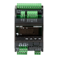
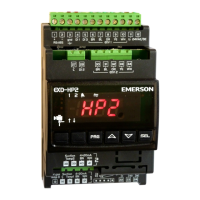
EXD-HP1/2 Controller with ModBus
communication capability
Emerson Climate Technologies GmbH www.emersonclimate.eu
Am Borsigturm 31 I 13507 Berlin I Germany Date: 08.09.2017 EXD-HP12_OI_ML_R03_865921.docx
Code Parameter description and choices Min Max
Low pressure alarm cut-in (bar) circuit 2
Freeze protection alarm function
1 = enable auto-reset,
Freeze alarm cut-out circuit2
Freeze protection alarm delay, sec.
Superheat control circuit2
(Kp factor), fixed PID
Superheat control circuit2 (Ti factor),
fixed PID
Superheat control circuit2 (Td factor),
fixed PID
High superheat alarm mode circuit 2
High superheat alarm setpoint (K) circuit 2
High superheat alarm delay (Min) circuit 2
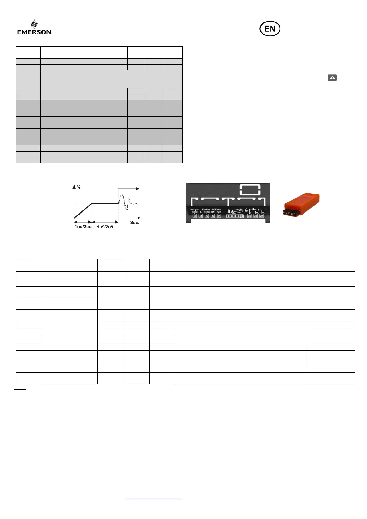
Control (valve) start-up behavior:
(Parameter 1uu/2uu and 1u9/2u9)
1uu/2uu:
Min.: 10% (<1 sec.)
Default: 20% (< 1.5 sec.)
Max.: 100% (< 6 sec.)
Upload/download Key: Function
• For serial production of systems/units, upload/download key allows the
transmission of configured parameters among range of identical systems.
Uploading procedure:
(storing configured parameters in key)
• Insert the key while the first (reference) controller is ON and press button;
the “uPL” message appears followed by “End” message for 5 seconds.
• Note: If the “Err” message is displayed for failed programming, repeat the above
procedure.
Downloading procedure:
(configured parameters from key to other controllers)
• Turn off power to new controller
• Insert a loaded Key (with stored data from reference controller) into new controller
and turn on the power supply.
• The stored parameters of the key will be downloaded automatically into the new
controller memory; The “doL” message appears followed by a “End” message for
5 seconds.
• The new controller with new loaded parameters setting will start to operate after
“End” message disappears.
• Remove the key.
• Note: If the “Err” message is displayed for failed programming, repeat the above
procedure.
Error/Alarm handling
Description
Valve What to do?
Requires manual reset
after resolving alarm
Pressure sensor 1/2 error
Check wiring connection and measure the signal 4 to 20 mA
Temperature sensor 1/2 error
Check wiring connection and measure the resistance of sensor
1Ed
Discharge hot gas
temperature sensor 3 error
- Triggered Operating Check wiring connection and measure the resistance of sensor No
1AΠ/2AΠ
EXM/EXL electrical
connection error
- Triggered - Check wiring connection and measure the resistance of winding No
1Ad
Discharge hot gas
temperature above limit
Triggered Operating
Check valve opening/ check liquid flow for flash gas free/check
discharge hot gas temperature sensor
No
Freeze protection
Check the system for cause of low pressure such as insufficient
load on evaporator
Low superheat
(<0,5K)
Check wiring connection and operation of valve
AP
Low pressure
1P9/2P9: 1 Triggered Operating
Check the system for cause of low pressure such as refrigerant
loss
No
Err
Failed
uploading/downloading
- - - Repeat again the procedure for uploading/downloading No
Note: When multiple alarms occur, the highest priority alarm is displayed until being cleared, then the next highest alarm is displayed until all alarms are cleared. Only then will
parameters be shown again.


 To Next Page
 Loading...