C1
C1
12
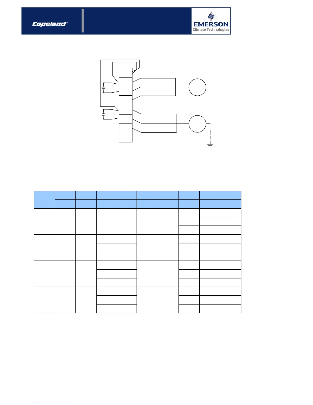
Figure 1: Single-phase wiring diagram (230V ±15% / 1 ~ / 50-60 Hz)
3.2 Three-phase fans
Before January 2003, three-phase fans were used.
3.2.1 Technical data
Blade
diamete
Power input Voltage
Motor
current
mm W V (±10%) / Ph / Hz A
220 - 240 / 1 / 50 0.36
220-240
∆
/ 380-420 Y /
3 / 50
0.33 / 0.19
500 - 550 / 3 / 50 0.15
220 - 240 / 1 / 50 0.63
220-240
∆
/ 380-420 Y /
3 / 50
0.55 / 0.32
500 - 550 / 3 / 50 0.25
220 - 240 / 1 / 50 1.3
220-240 ∆ / 380-420 Y /
3 / 50
1.10 / 0.65
500 - 550 / 3 / 50 0.52
220 - 240 / 1 / 50 3.6
220-240 ∆ / 380-420 Y /
3 / 50
2.95 / 1.70
500 - 550 / 3 / 50 1.1
9.3
Winding resistance
5 / 400
8 / 400
16 / 400
25 / 400
20 / 60
51
6.2
6.2 / 18.6
54.7
57 ± 3 / 172 ± 10
325 ± 24
20
Ω (±10%), 25°C
102
104 ± 3 / 218 ± 6
574 ± 37
270 420 280
610 500 630
Fan model
75 300 80
Run capacitor
µF / V
120 350 135
Table 2: Technical data – three-phase fans
“Old” units were delivered with three-phase fans as a standard, but it is possible to convert these fans into single-
phase motor by the mean of a capacitor. The characteristics of this run capacitor are given in table 2.
“New” single-phase kits can be used for retrofitting on units equipped with three-phase fans.
fan 75 is replaced by 71
fan 120 is replaced by 121
fan 210 is replaced by 211
fan 610 is replaced by 611
2/4