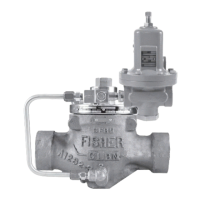
133 Series
11
6. Assemble the upper and lower casings, noting
that two of the holes in the 5-1/4-inch (133 mm)
diameter bolt circle in the mounting plate adaptor
must be spaced (aligned) an equal distance over
the downstream control line connection. Install
cap screws and hex nuts (keys 35 and 36) with a
torque of 20 to 30 foot-pounds.
7. Place the balancing plate washer (Figure 15,
key 23), balancing diaphragm plate (key 21),
balancing diaphragm (key 22) and a second
balancing plate washer (key 23), onto the stem
(key 18).
Note
When installing the balancing
diaphragm, be certain the side marked
PISTON SIDE is facing the spring case.
Carefully tuck the slack diaphragm
material into the space between the
diaphragm plate and lower casing
(Figure 6, key 7) until the diaphragm
ts smoothly over the diaphragm
plate without wrinkles and the bead
ts snugly and evenly in the groove
provided in the lower casing.
8. Apply Magnalube-G or equivalent to the sealing
washer (key 17) and carefully slide over the
threaded end of the stem (key 18).
9. Insert the guide bushing (key 24) into the cage
(key 5), and slide the cage up onto the stem.
Insert the set screws (key 39) only far enough to
retain the cage. Do not tighten.
10. Install the orice (key 2) onto the cage (key 5).
Install the Belleville spring washer (key 3) so that
the concave face of the washer faces away from
the orice.
11. Install the E-ring (key 26) on the stem sleeve
(key 25) and slide the stem sleeve over the stem
aligning the slotted end of the stem sleeve so
that the roll pin (key 27) can be inserted through
the cross-drilled hole in the end of the stem.
CAUTION
Always use the stem sleeve wrench
ats when loosening or tightening the
nuts (keys 20 or 31) to prevent twisting
of the main and balancing diaphragms
(keys 15 and 22).
12. Install the valve disk (key 28), registration disk
(key 29), washer (key 30) and hex nut (key 31)
onto the stem. The registration disk (key 29)
is marked for proper placement; be certain it
is positioned correctly on the stem (key 18).
Tighten the hex nut (key 31) using the 1/2-inch
(12,7 mm) wrench ats on the stem sleeve.
13. Insert the valve trim assembly into the body
and position the downstream control line
connection (key 51) so it is pointing directly over
the body outlet.
14. Install and tighten the hex nuts (key 34) to
28 to 32 foot-pounds of torque.
15. Apply anti-seize to the adjusting screw (key 11)
and upper spring seat (key 41). Install the
adjusting screw and hex jam nut (key 59) into the
spring case (key 8). Position the control spring
(key 12) and upper spring seat on the diaphragm
plate (key 14) and lower spring seat (key 13).
16. Install the mounting plate gasket (key 57) and
place the spring case on the mounting bracket
(key 56). Install the cap screws (key 62) and
torque to 18 to 22 foot-pounds.
17. Screw in the pipe nipple (key 49) and vent
(key 50). Install the closing cap gasket (key 10)
and closing cap (key 9).
Parts Ordering
When corresponding with your local Sales ofce about
this equipment, be sure to include the type number and
other information stamped on the nameplate.
When ordering replacement parts, reference the key
number of each needed part and specify the eleven
character part number as found in the following parts list.
Parts List
Key Description Part Number
Parts kit for Types 133H, 133L, and 133Z
(included are keys 2, 4, 6, 10, 15, 17, 19, 24,
28, 32, and 40) R133HX00012
1 Body
Cast iron
NPT 30A3044X012
CL125 FF 30A3045X012
Steel
NPT 30B0855X012
CL150 RF 30B0854X012
2* Orice, aluminum 20A3046X012
3 Belleville Spring Washer, 17-4PH 10A3047X012
4* O-Ring, Nitrile (NBR) 10A9339X012
* Recommended spare parts.

 Loading...

