www.Fisher.com
Fisherr 249 Cageless Displacer Sensors
Contents
Introduction 1.................................
Scope of Manual 1.............................
Description 1.................................
Type Number Description 2.....................
Educational Services 3.........................
Maintenance 3.................................
Removing the Displacer and Stem 4..............
Replacing the Displacer, Cotter Spring,
Stem End Piece, and Displacer Spud 6..........
Replacing the Displacer Rod/Driver Assembly 7....
Replacing the Torque Tube 8....................
Replacing the Torque Tube Arm and
Changing the Mounting 9....................
Simulation of Process Conditions for
Calibration of Fisher Level Controllers
and Transmitters 10............................
Parts Ordering 10...............................
Parts Kits 11...................................
Parts List 11...................................
Sensor Common Parts 11.......................
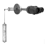
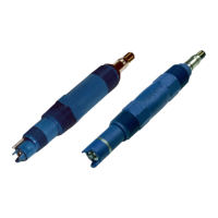
Figure 1. Fisher 249V Sensor with FIELDVUE™
DLC3010/DLC3020f Digital Level Controller
W3120‐3
Introduction
Scope of Manual
This instruction manual includes maintenance and parts ordering information for Fisher 249 cageless displacer
sensors.
Although a 249 sensor is usually shipped with attached controller or transmitter, this manual does not include
operation, installation, calibration, maintenance, and parts ordering information for the controller/transmitter or for
the complete unit. For this information, refer to the appropriate controller/ transmitter instruction manual.
Do not install, operate, or maintain a 249 sensor without being fully trained and qualified in valve, actuator, and
accessory installation, operation, and maintenance. To avoid personal injury or property damage, it is important
to carefully read, understand, and follow all of the contents of this manual, including all safety cautions and
warnings. If you have any questions about these instructions, contact your Emerson Process Management sales office
.
Description
249 sensors are designed to measure liquid level, interface level, or density/specific gravity inside a process vessel.
Instruction Manual
D200100X012
249 Cageless Sensors
July 2015