Do you have a question about the Emerson Micro Motion Elite Coriolis Micro Motion Elite Coriolis CMF025 and is the answer not in the manual?
Steps to ensure proper installation of the Micro Motion sensor.
Guidelines for optimal sensor performance and longevity.
Operational ambient and process temperature ranges for sensors and electronics.
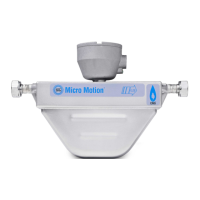
Installation guidelines for hygienic and self-draining process applications.
Procedures for safely lifting and transporting heavy sensor units.
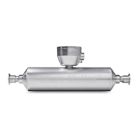
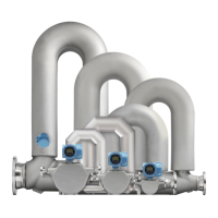
Step-by-step guide for mounting the sensor into the process pipeline.
Instructions for rotating the junction box or core processor for optimal orientation.
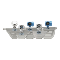
Mounting the separate electronics for high-temperature sensor applications.
Optional mounting configuration for CMF010 sensors to walls or poles.
Optional bracket mounting procedure for CMFS007, CMFS010, and CMFS015 sensors.
Optional wall mount bracket installation for CMFS025, CMFS040, and CMFS050 sensors.
Method for clamping wafer-style sensors into the pipeline using an installation kit.
Procedure for installing the extender onto the sensor case for extended electronics.
Guide to wiring procedures based on the sensor's electronics option.
Instructions for preparing and connecting 4-wire cables for power and signal.
Instructions for preparing and connecting 9-wire cables for signal transmission.
Guidelines and steps for proper grounding of the flowmeter to ensure safety and accuracy.
Procedure for purging the sensor case with inert gas to remove oxygen.
Information on the rupture disk installed for venting process fluid in case of tube breach.
| Model | CMF025 |
|---|---|
| Brand | Emerson Micro Motion |
| Material | 316L Stainless Steel |
| Output | 4-20 mA, Pulse, Frequency |
| Communication | HART, Modbus, Foundation Fieldbus |
| Power Supply | 24 VDC |
| Type | Coriolis Flow Meter |
| Connection Type | Flanged, Threaded |
| Size | 1/4 inch |