Do you have a question about the Emerson Micro Motion Elite Coriolis CMF400 and is the answer not in the manual?
Verify installation suitability, environment, and meter limits.
Guidelines for optimal sensor performance and installation.
Ambient and process temperature operating ranges for sensors.
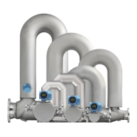
Installation guidelines for sanitary and self-draining systems.
Guidance on safely lifting and handling heavy sensor units.
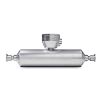
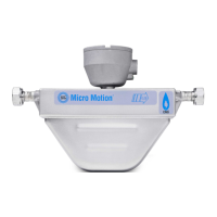
Procedures for correctly installing the sensor into the pipeline.
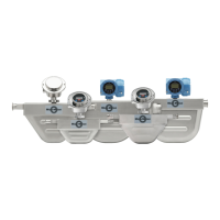
Steps to adjust the orientation of the junction box or core processor.
Instructions for mounting remote electronics for high-temperature sensors.
Procedures for mounting CMF010 sensors using optional brackets.
How to install CMFS007/010/015 sensors using a mounting bracket.
Steps to mount CMFS025/040/050 sensors with a wall bracket.
Method for securing wafer-style sensor connections in the pipeline.
Procedure for connecting extended electronics to the sensor.
Overview of wiring procedures based on available electronics options.
Detailed steps for preparing and connecting a 4-wire cable to the sensor.
Instructions for preparing and connecting a 9-wire cable.
Procedure for purging the sensor case with inert gas.
Information about the sensor's rupture disk and pressure relief features.
| Measurement Principle | Coriolis |
|---|---|
| Temperature Range | -50°C to 150°C (-58°F to 302°F) |
| Power Supply | 24 VDC |
| Pressure Rating | Varies by model |
| Output Signal | 4-20 mA |
| Material | Stainless Steel |
| Accessory Type | Flow Meter |
| Application | flow measurement |
| Communication Protocol | HART, Modbus, Foundation Fieldbus |