Instruction Manual
D103292X012
C1 Controllers and Transmitters
March 2017
8
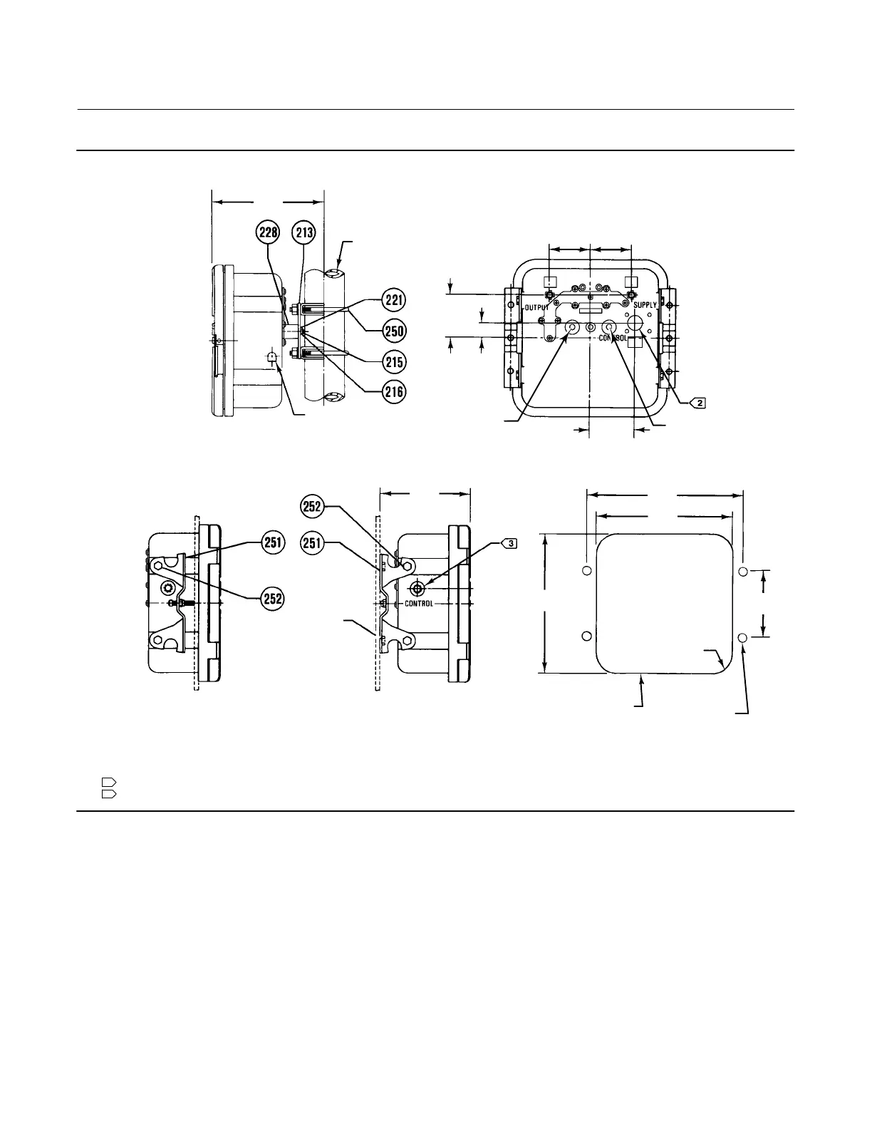
Figure 2. Panel, Wall, and Pipestand Mounting
2 INCH
(NOMINAL)
PIPE
VENT ASSEMBLY
(KEY 28)
FOUR HOLES
FOR WALL
MOUNTING
CUTOUT FOR
PANEL MOUNTING
MOUNTING
HOLES
PANEL MOUNTING WALL MOUNTING
BACK VIEW
PIPESTAND MOUNTING
mm
(INCH)
NOTES:
1. ALL CONNECTIONS ARE 1/4 NPT INTERNAL.
HIGH-PRESSURE CONNECTION FOR DIFFERENTIAL-PRESSURE UNITS.
2
3
LOW-PRESSURE CONNECTION FOR DIFFERENTIAL-PRESSURE UNITS.
E1052
101.6
(4.00)
14.3
(0.56) R
244.3
(9.62)
215.9
(8.50)
218.9
(8.62)
142.7
(5.62)
69.1
(2.72)
23.1
(0.91)
65.8
(2.59)
63.5
(2.50)
63.5
(2.50)
180.8
(7.12)
8.7
(11/32)
KNOCK-OUT
KNOCK-OUT
 Loading...