Instruction Manual
D103597X012
D4 Valve with easy-Drive Actuator
October 2017
7
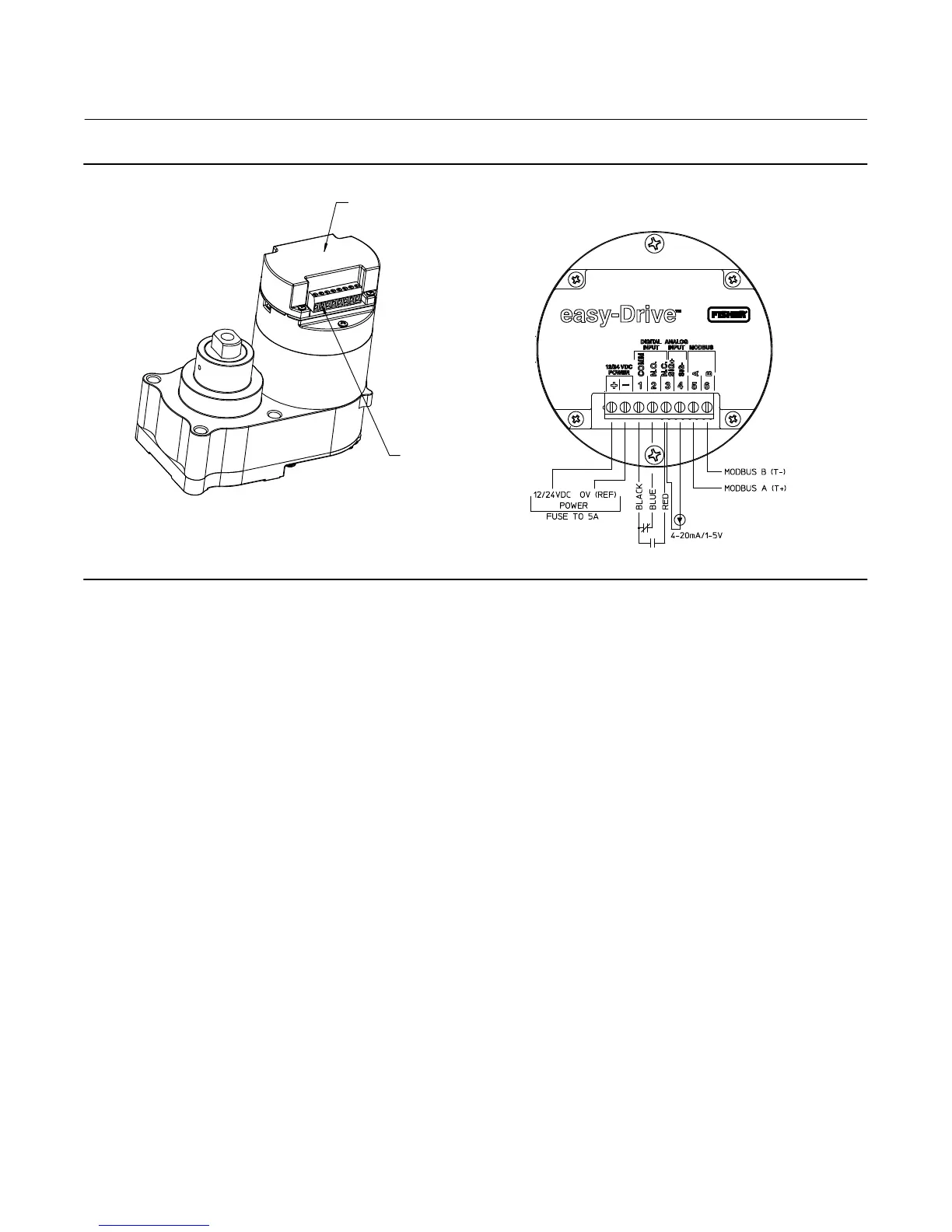
Figure 3. Fisher D4 Valve with easy-Drive Actuator Wiring Diagram
FIELD WIRING CONNECTIONS
MOTOR / GEARBOX ASSY
(GE48474)
CONTROLLER
POWER AND
CONTROL TERMINAL
GE47302-7
TOP VIEW CONTROLLER
Power Requirements
Ensure a stable DC power source is available, maintaining less than 5% ripple and sufficiently surge protected for the
application. A 4 amp (minimum) power supply is required. Use of a 36 volt transient voltage suppressor is highly
recommended.
Wiring Instructions
1. Observe local wiring requirements for hazardous location usage.
2. Conduit seals within 457 mm (18 inches) of the enclosure port are required for explosionproof installation.
3. 22AWG (0.33mm
2
) to 12AWG (3.31mm
2
) wire size required.
4. Fuse system to 5A.
5. Connect enclosure and analog signal shields.
6. Ensure power is turned off before connecting the wires.
Power
1. Connect 12 or 24 VDC reference to: –
2. Connect 12 or 24 VDC positive to: +
3. Be sure to tighten terminals sufficiently to ensure solid mechanical connection.

 Loading...


