Instruction Manual
D103597X012
D4 Valve with easy-Drive Actuator
October 2017
8
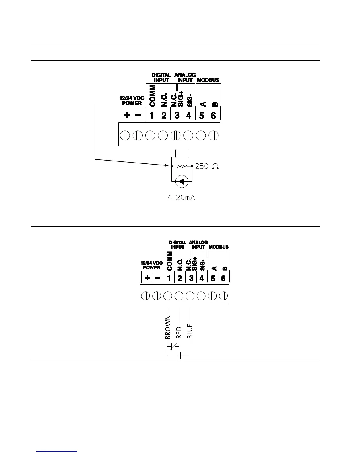
Figure 4. Wiring - Analog Input
Analog Input
(420mA: 40033=1, 40034=1, 40043=0
(1)
)
1. Connect signal to terminal 3
2. Connect reference to terminal 4
3. Connect 250 ohm resistor between
terminals 3 and 4 as shown.
NOTE:
1. 40043=0 SETS ANALOG INPUT TO 1-5V AND ASSUMES USE OF RECOMMENDED EXTERNAL 250 OHM RESISTOR.
IF NO EXTERNAL RESISTOR IS USED, SET 40043=1.
Figure 5. Wiring - L2e
L2e (dual dry contact:
40033=0, 40034=0, 40043=0)
1. Connect L2e brown wire to terminal 1 (COMM (com))
2. Connect L2e red wire to terminal 2 (N.O. (OPEN))
3. Connect L2e blue wire to terminal 3 (N.C. (CLOSE))
Your actuator may be labelled:
1. COMM
2. N.O.
3. N.C.
or
1. com
2. OPEN
3. CLOSE

 Loading...


