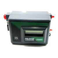
DVC2000 Digital Valve Controller
July 2009
1-4
Table 1-1. Specifications
Available Configurations
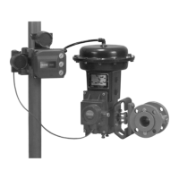
Integral mounting to the Fisher GX Control Valve
and Actuator System
Sliding-stem applications
Quarter-turn rotary applications
The DVC2000 digital valve controller can also be
mounted on other actuators that comply with IEC
60534-6-1, IEC 60534-6-2, VDI/VDE 3845 and
NAMUR mounting standards.
Input Signal
Analog Input Signal: 4−20 mA DC, nominal; split
ranging available
Minimum Voltage: Voltage available at instrument
terminals must be 8.5 volts for analog control, 9.0
volts for HART communication
Maximum Voltage: 30 volts DC
Minimum Control Current: 4.0 mA (below 3.5 mA
may cause microprocessor restart)
Overcurrent Protection: Input circuitry limits current
to prevent internal damage
Reverse Polarity Protection: No damage occurs
from reversal of loop current
Output Signal
Pneumatic signal as required by the actuator, up to
95% of supply pressure
Minimum Span: 0.5 bar (7 psig)
Maximum Span: 7 bar (101 psig)
Action: Single Acting, direct
Supply Pressure
(1)
Recommended: 0.5 bar (7 psig) greater than the
maximum actuator requirements
Maximum: 7 bar (101 psig)
Supply pressure must be clean, dry air or
nonflammable, noncorrosive gas that meets the
requirements of ISA Standard 7.0.01. A maximum
40 micrometer particle size in the air system is
acceptable. Further filtration down to 5 micrometer
particle size is recommended. Lubricant content is
not to exceed 1 ppm weight (w/w) or volume (v/v)
basis. Condensation in the air supply should be
minimized
Temperature Limits
(1)
−40 to 85C (−40 to 185F). LCD may not be
readable below −20C (−4 F).
Air Consumption
(2)
Supply pressure:
At 1.5 bar (22 psig)
(3)
: 0.06 normal m
3
/h (2.3 scfh)
At 4 bar (58 psig)
(4)
: 0.12 normal m
3
/h (4.4 scfh)
Air Capacity
(2)
Supply pressure:
At 1.5 bar (22 psig)
(3)
: 4.48 normal m
3
/h (167 scfh)
At 4 bar (58 psig)
(4)
: 9.06 normal m
3
/h (338 scfh)
Independent Linearity
±0.5% of output span
Electromagnetic Compatibility
Meets EN 61326-1 (First Edition)
Immunity—Industrial locations per Table 2 of the
EN 61326-1 standard. Performance is shown
in table 1-2 below
Emissions—Class A
ISM equipment rating: Group 1, Class A
Tested to NAMUR NE21 requirements.
Vibration Testing Method
Tested per ANSI/ISA 75.13.01 Section 5.3.5. A
resonant frequency search is performed on all three
axes. The instrument is subjected to the ISA
specified 1/2 hour endurance test at each major
resonance, plus an additional two million cycles.
Input Impedance
The input impedance of the DVC2000 active
electronic circuit is not purely resistive. For
comparison to resistive load specifications, an
equivalent impedance of 450 ohms may be used.
This value corresponds to 9 V @ 20 mA.
Electrical Classification
Hazardous Area:
CSA—Intrinsic Safety and Non-incendive
FM—Intrinsic Safety and Non-incendive
ATEX—Intrinsic Safety
IECEx—Intrinsic Safety
NEPSI—Intrinsic Safety
Refer to the Special Instructions for Safe Use and
Installations in Hazardous Locations, tables 1-3,
1-4, 1-5, 1-6, and 1-7, and figures C-1, C-2, C-3,
C-4, C-5, C-6, and C-7 for additional information.
Electrical Housing: IP66
−continued−
1

 Loading...


