EasyManua.ls Logo

Emerson Fisher Fieldvue DVC6010f User Manual

Emerson Fisher Fieldvue DVC6010f
376 pages
To Next Page IconTo Next Page
To Previous Page IconTo Previous Page
Page #153 background imageLoading...
Page #153 background image
PID Function Block
March 2006
5-87
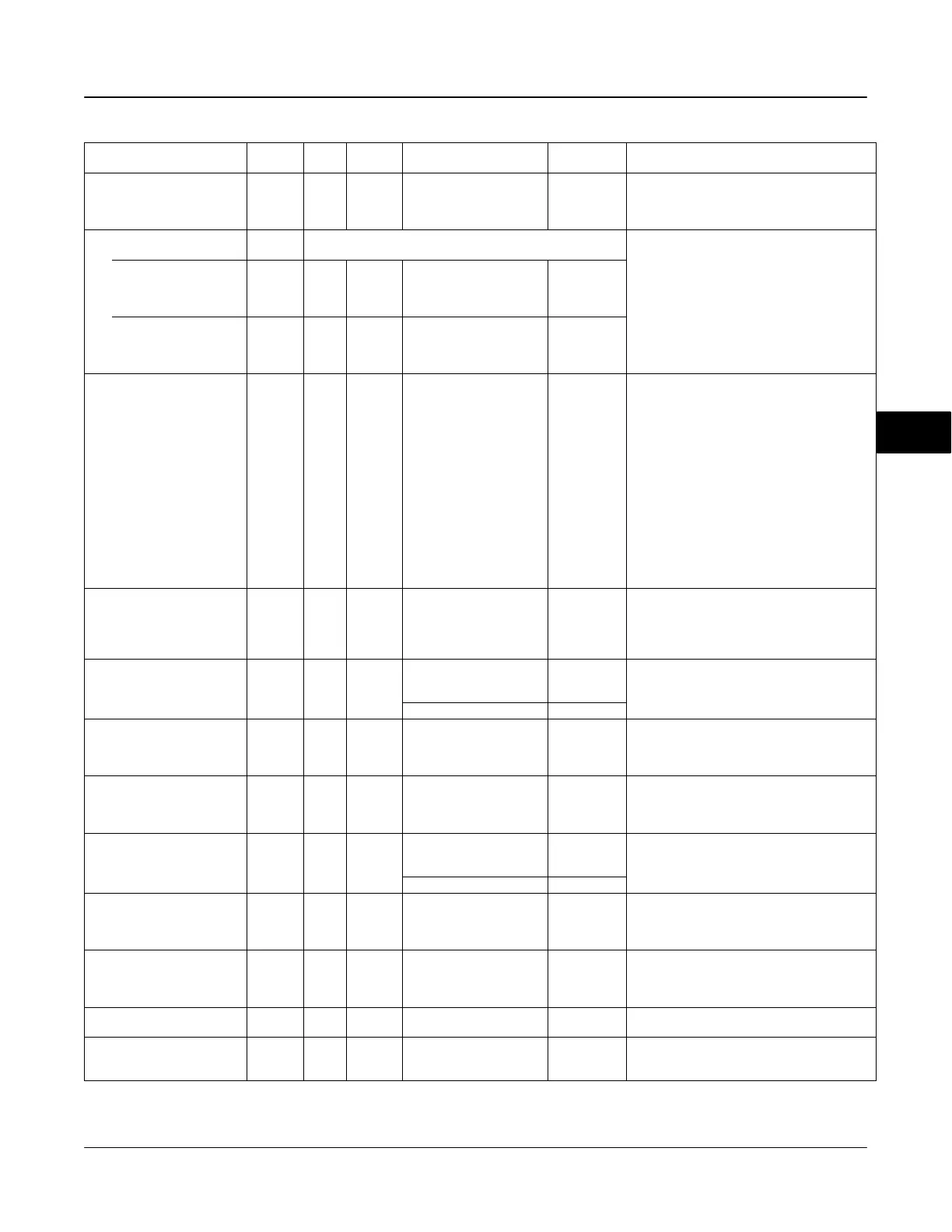
Table 5-31. PID Function Block System Parameters Definitions (Continued)
Label
PARAMETER_NAME
DescriptionInitial ValueRange
Block
Mode
RO /
RW
Index
Number
Output Scale
OUT_SCALE
11 OOS
EU at 100%
EU at 0%t
Units index
Decimal
Point
100
0
%
2
Data Type: DS-68
The high and low scale values, engineering units
code, and number of digits to the right of the
decimal point associated with OUT.
Grant Deny
GRANT_DENY
12
Data Type: DS-70
Options for controlling access of host computers
and local control panels to operating, tuning, and
alarm parameters of the block. Not used by the
device.
GRANT: 0=N/A, 1=granted
DENY: 0 = N/A, 1= denied
GRANT 12.1 ALL
0: Program
1: Tune
2: Alarm
3: Local
All bits: 0
DENY 12.2 ALL
0: Program
1: Tune
2: Alarm
3: Local
All bits: 0
Control Options
CONTROL_OPTS
13 OOS
0: Bypass Enable
1: SP tracks PV in MAN
2: SP tracks PV in ROUT
3: SP tracks PV in LO or
MAN
4: SP tracks RCAS or CAS
in IMAN, LO, MAN or
ROUT
5: Direct Acting
7: Track Enable
8: Track in Manual
9: Use PV for BKCAL_OUT
10: Act on IR
12: Restrict SP to limits in
Cas and RCas
13: No output limits in MAN
All bits: 0
Data Type: Bit String
0=disable
1=enable
Allows you to specify control strategy options.
Status Options
STATUS_OPTS
14 OOS
0: IFS (Initiate Fault State)
if BAD IN
1: IFS if BAD CAS_IN
2: Use Uncertain as Good
5: Target to MAN if BAD IN
All bits: 0
Data Type: Bit String
0=disable
1=enable
Allows you to select options for status handling
and processing.
Input
IN
15 ALL
Status
BAD:
NC:
const
Data Type: DS-65
The primary input value of the block.
Value 0
Process Value Filter Time
PV_FTIME
16 ALL Positive 0
Data Type: Float
The time constant of the firstorder PV filter. It is
the time, in seconds, required for a 63 percent
change in the IN value.
Bypass
BYPASS
17
MAN
OOS
1=Off
2=On
0=undefined
Data Type: Enum
Used to override the calculation of the block.
When enabled, the SP is sent directly to the
output.
Cascade Input
CAS_IN
18 ALL
Status
BAD
NC:
const
Data Type: DS-65
The setpoint value from another block.
Value 0
Setpoint Rate Down
SP_RATE_DN
19 ALL Positive + INF
Data Type: Float
Ramp rate for downward SP changes. When the
ramp rate is set to zero, the SP is used
immediately. PV per second
Setpoint Rate UP
SP_RATE_UP
20 ALL Positive + INF
Data Type: Float
Ramp rate for upward SP changes. When the
ramp rate is set to zero, the SP is used
immediately. PV per second
Setpoint High Limit
SP_HI_LIM
21 ALL
PV Scale +/ 10%, must be
greater than SP_LO_LIM
100
Data Type: Float
The highest SP value allowed.
Setpoint Low Limit
SP_LO_LIM
22 ALL
PV Scale
+/ 10%, must be less than
SP_HI_LIM
0
Data Type: Float
The lowest SP value allowed.
Continued
5

Table of Contents

Question and Answer IconNeed help?

Do you have a question about the Emerson Fisher Fieldvue DVC6010f and is the answer not in the manual?

Emerson Fisher Fieldvue DVC6010f Specifications

General IconGeneral
BrandEmerson
ModelFisher Fieldvue DVC6010f
CategoryController
LanguageEnglish

Summary

Introduction

Scope of Manual

Details specifications, installation, operation, and maintenance for DVC6000f Series digital valve controllers.

Instrument Description

Overview of DVC6000f Series digital valve controllers for FOUNDATION fieldbus.

Specifications

Technical specifications for DVC6000f Series digital valve controllers.

Installation

Special Instructions for Safe Use and Installation in Hazardous Locations

Provides specific safety conditions for hazardous locations based on approvals (CSA, FM, ATEX, IECEx).

Mounting

Guidelines for mounting DVC6000f Series controllers on various actuator types.

375 Field Communicator Basics

Online Operation

Describes how to view device data and connect to a Fieldbus loop.

Function Blocks

Transducer Block

Overview of the transducer block, its modes, and parameters.

Resource Block

Information on the resource block, including modes, write lock, and alarms.

Analog Output (AO) Function Block

Details on the AO function block, including modes, mode handling, and parameter list.

PID Function Block

Explanation of the PID function block, its modes, and parameters.

Analog Input (AI) Function Block

Information on the AI function block, including modes, signal conversion, and advanced features.

Calibration

Travel Calibration

Procedures for calibrating travel: Auto and Manual.

Travel Sensor Adjust

Procedures for adjusting the travel sensor using a multimeter or Field Communicator.

Pressure Sensor Calibration

Procedures for calibrating supply, output A, and output B pressure sensors.

Maintenance and Troubleshooting

Module Base Maintenance

Procedures for removing and replacing the module base assembly.

SubModule Maintenance

Maintenance procedures for I/P converter, PWB assembly, and pneumatic relay.

Instrument Troubleshooting

Troubleshooting guide for common instrument issues.

Parts

Parts List

Comprehensive list of common parts, submodules, and assemblies.

FOUNDATION fieldbus Communication

Function Block Overview

Explains function blocks, instrument-specific blocks, and resource/transducer blocks.

Device Description (DD) Installation

Operating with DeltaV™

Getting Started with DeltaV™ Host Systems

Steps for initial setup, including DD installation and device commissioning.

Loop Schematics/Nameplates

Related product manuals