Principle of Operation
March 2006
8-3
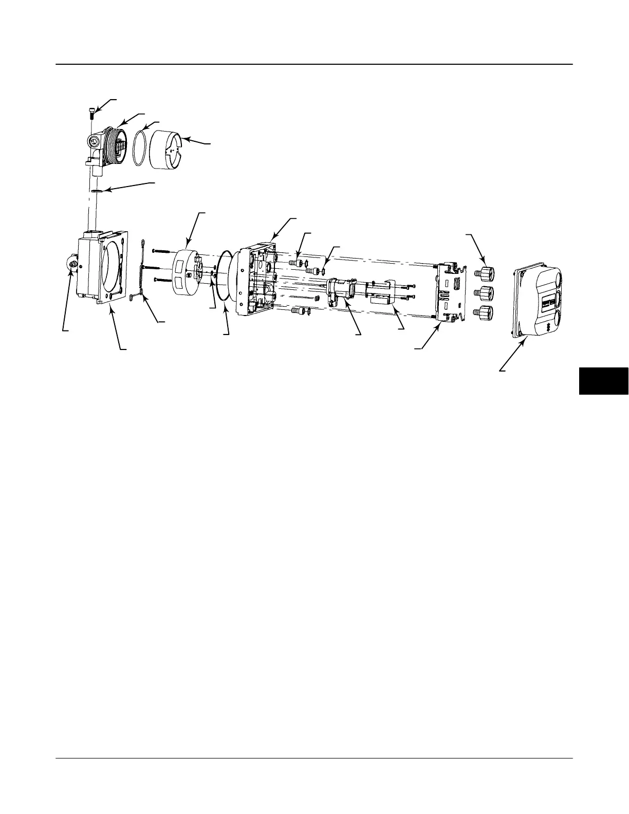
Figure 8-2 . DVC6000f Series Digital Valve Controller Assembly
TERMINAL BOX COVER
TERMINAL BOX ASSEMBLY
HOUSING
MODULE BASE
SEAL
PRINTED WIRING BOARD
ASSEMBLY
PNEUMATIC RELAY
I/P CONVERTER
MODULE BASE ASSEMBLY
PRESSURE
GAUGES
(OPTIONAL)
TRAVEL
SENSOR
ASSEMBLY
COVER
ASSEMBLY
48B7710
E0515 / IL
SOCKET-HEAD SCREWS (3)
RETAINING CLIPS (3)
SHROUD
0-RINGS (3)
SOCKET-HEAD SCREW
O-RING
O-RING
O-RING
As shown in figure 8-1, the increased output A
pressure causes the actuator stem to move upward.
Stem position is sensed through the feedback linkage
by the travel sensor which is electrically connected to
the printed wiring board assembly submodule. The
stem continues to move downward until the correct
stem position is attained. At this point the printed
wiring board assembly stabilizes the I/P drive signal.
This prevents any further increase in the pneumatic
signal from the I/P converter.
As the digital setpoint decreases, the drive signal to
the I/P converter submodule decreases, decreasing
the I/P output pressure. The pneumatic relay
decreases the output A pressure and increases the
output B pressure. The stem moves downward until
the correct position is attained. At this point the printed
wiring board assembly stabilizes the I/P drive signal.
This prevents any decrease in the pneumatic signal
from the I/P converter.
8
 Loading...


