Basic Setup and Tuning
March 2006
4-3
Note
If a Type B, reverse acting relay is
used, you must manually set the Relay
Type (BASIC_SETUP.RELAY_TYPE
[42.5]) to B. This will not be set during
Setup Wizard.
1. Select whether Travel, Travel with Pressure
fallback (auto recovery or manual recovery) or
Pressure Control is desired. Refer to page 5-23 for
additional information.
2. Enter the pressure units:kPa, bar, psi, inHg or in
H
2
O
3. Enter the maximum instrument supply pressure
and output pressure range (if required).
4. Enter the manufacturer of the actuator on which
the instrument is mounted. If the actuator
manufacturer is not listed, select Other.
5. Enter the actuator model or type. If the actuator
model is not listed, select Other.
6. Enter the actuator size.
7. Indicate whether a Volume Booster is being used.
8. Specify if factory defaults should be used for basic
setup. If you select YES for factory default, the Field
Communicator sets the setup parameters to the
values listed in table 4-1. If you select NO for the
factory defaults, the setup parameters listed in the
table remain at their previous settings.
Typically the Setup Wizard determines the required
setup information based upon the actuator
manufacturer and model specified. However, if you
enter other for the actuator manufacturer or the
actuator model, then you will be prompted for setup
parameters such as:
Actuator Style—Select spring & diaphragm,
piston double-acting without spring, piston
single-acting with spring, piston double-acting with
spring.
Valve Style—Select the valve style, rotary or
sliding stem.
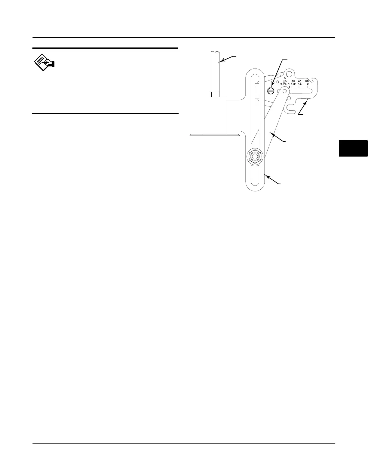
ACTUATOR
STEM
TRAVEL SENSOR SHAFT
FEEDBACK ARM
CONNECTOR ARM
ADJUSTMENT ARM
Figure 4-1. Feedback Connection for Typical Sliding-Stem
Actuator (Up to 4-inch Travel)
A6536-1 / IL
Zero Power Condition—Identifies whether the
valve is fully open or fully closed when instrument
power is lost. If you are unsure how to set this
parameter, disconnect the segment loop power to the
instrument. The resulting valve travel is the Zero
Power Condition.
Feedback Connection—Select Rot-All, SS-roller,
or SStem-Standard. For rotary valves, enter Rot - All,
SS-Roller. For sliding-stem valves, if the feedback
linkage consists of a connector arm, adjustment arm,
and feedback arm, similar to the linkage shown in
figure 4-1, enter SStem - Standard. If the feedback
linkage consists of a roller that follows a cam, similar
to the linkage shown in figure 4-2, enter Rotary All,
SS-Roller.
Travel Sensor Motion—Select Clockwise or
Counterclockwise. Travel Sensor Motion establishes
the proper valve travel sensor (feedback) rotation.
Determine the rotation by viewing the end of the travel
sensor shaft.
4
 Loading...


