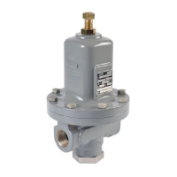
MR95 Series
3
To avoid such injury or damage, provide
pressure-relieving or pressure-limiting devices
(as required by the appropriate code, regulation
or standard) to prevent service conditions from
exceeding limits.
Additionally, physical damage to the regulator
could result in personal injury and property
damage due to escaping fluid. To avoid such
injury and damage, install the regulator in a
safe location.
Clean out all pipelines before installation of the regulator and check
to be sure the regulator has not been damaged or has collected
foreign material during shipping. For NPT bodies, apply pipe
compound to the external pipe threads. For flanged bodies, use
suitable line gaskets and approved piping and bolting practices.
Install the regulator in any position desired, unless otherwise
specified, but be sure flow through the body is in the direction
indicated by the arrow on the body.
Note
It is important that the regulator be installed
so that the vent hole in the spring case
is unobstructed at all times. For outdoor
installations, the regulator should be located away
from vehicular traffic and positioned so that water,
ice and other foreign materials cannot enter the
spring case through the vent. Avoid placing the
regulator beneath eaves or downspouts and be
sure it is above the probable snow level.
Overpressure Protection
The recommended pressure limitations are stamped on the
regulator nameplate. Some type of overpressure protection is
needed if the actual inlet pressure exceeds the maximum operating
outlet pressure rating. Overpressure protection should also be
provided if the regulator inlet pressure is greater than the safe
working pressure of the downstream equipment.
Regulator operation below the maximum pressure limitations does
not preclude the possibility of damage from external sources or
debris in the line. The regulator should be inspected for damage
after any overpressure condition.
Startup
The regulator is factory set at approximately the midpoint of the
spring range or the pressure requested, so an initial adjustment
may be required to give the desired results. With proper installation
completed and relief valves properly adjusted, slowly open the
upstream and downstream shutoff valves.
Adjustment
To change the outlet pressure, loosen the jam nut and turn
the adjusting screw clockwise to increase outlet pressure or
counterclockwise to decrease it. Monitor the outlet pressure with a
test gauge during the adjustment. Tighten the jam nut to maintain
the desired setting.
Taking Out of Service (Shutdown)
!
WARNING
To avoid personal injury resulting from sudden
release of pressure, isolate the regulator from all
pressure before attempting disassembly.
*Recommended Spare Part
1. Only one metal diaphragm is needed for Types MR95L and MR95LD with 1/4 NPT body
size and 0.14 to 0.41 bar / 2 to 6 psi spring range.
Parts List
Key Description
1 Body
2 Spring Case
3* Orifice
4* Valve Plug, Metal seat
4* Disk Holder Assembly, Composition seat
4a Disk Holder
4b Disk
4c O-ring, Type MR95HP only (not shown)
5 Valve Plug Guide
6 Stem/Stem Assembly
6a Stem
6b Pusher Plate
6b O-ring
6c O-ring
7 Stem Guide Bushing
8 Lower Spring Seat
9 Upper Spring Seat
10 Pusher Post, (not shown)
11 Control Spring
12* Diaphragm
(1)
13 Nameplate
14* Diaphragm Protector (not shown)
15 Adjusting Screw
16 Cap Screw
17 Jam Nut
18 Nameplate Drive Screw
19* Diaphragm Gasket
20 Pitot Tube (for constructions without control line)
21 Diaphragm Head Assembly,Types MR95L and MR95LD only
(not shown)
21a Diaphragm Head
21b Lower Spring Seat
21c Screw
21 Diaphragm Head (not shown)
22 Adjusting Screw Assembly (Tee Handle Adjustment)
23 Handwheel (not shown)
26 Inner Valve Spring
27 Inner Valve Base (not shown)
27 Inner Valve Base Assembly, Type MR95HP only (not shown)
29* Gasket (not shown)
31 Locknut (not shown)
32 Stuffing Box
33 Adjusting Screw
34 Packing Follower
35 Stuffing Box Nut
36 Packing
37* Stuff Box Gasket
38 Handwheel/Handle
39 Internal Adaptor
40 External Adaptor
41 Machine Screw
41 Jam Nut, Types MR95HD and MR95HDP only
42 Spring
43 Washer
44 Washer
45* O-ring, Types MR95HD and MR95HDP only (not shown)
47 NACE Tag (not shown)
48 Tag Wire (not shown)
49 Lockwasher (not shown)
50* Sealing Washer
51 Vent, Type Y602-12 (not shown)
52 Plug
62 Adaptor, Types MR95L and MR95LD only (not shown)
63* Bottom Plug Seal
64 Flow Arrow
65 Pipe Plug (not shown)
66 Inlet Pressure Gauge (not shown)
67 Outlet Pressure Gauge (not shown)
69 ATEX Tag (not shown)
70 PED Tag (not shown)
 Loading...


