Type 99
8
Clean out all pipelines before installation and check
to be sure the regulator has not been damaged or
collected foreign material during shipping.
Apply pipe compound to the external pipe threads
only with a threaded body or use suitable line gaskets
and good bolting practices with a anged body. This
regulator may be installed in any position desired as
long as the ow through the body is in the direction
indicated by the arrow on the body. Install a three-valve
bypass around the regulator if continuous operation is
necessary during maintenance or inspection.
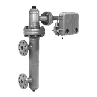
Although the standard orientation of the actuator and
pilot to the main valve body is as shown in Figure 1, this
orientation may be changed as far as the inlet tubing
(key 24, Figure 9 or 17) will permit by loosening the
union nut (key 14, Figure 9), rotating the actuator lower
casing (key 29, Figure 9) as desired and tightening
the union nut. To keep the pilot spring case from being
plugged or the spring case from collecting moisture,
corrosive chemicals or other foreign material, the vent
must be pointed down, oriented to the lowest possible
point on the spring case or otherwise protected. Vent
orientation may be changed by rotating the spring case
with respect to the pilot body.
To remotely vent a low-pressure pilot, install the vent
line in place of the pressed-in vent assembly (key 60,
Figure 9). Install obstruction-free tubing or piping into
the 1/4 in. / 6.4 mm vent tapping. Provide protection
on a remote vent by installing a screened vent cap into
the remote end of the vent pipe.
To remotely vent a high-pressure pilot, remove the
threaded-in vent assembly (key 72, Figure 12)
from the high-pressure pilot spring case and install
obstruction-free tubing or piping into the 1/4 in. /
6.4 mm vent tapping. Provide protection on a remote
vent by installing a screened vent cap into the remote
end of the vent pipe.
An upstream pilot supply line is not required
because of the integral pilot supply tubing (key 24,
Figure 9 or 17). However, as long as the 1/4 NPT
tapping in the main valve body is plugged, this
tubing may be disconnected from both the main
valve and lter assembly (key 75, Figures 9 and 16)
in order to install a pilot supply line from a desired
remote location into the lter.
If the maximum pilot inlet pressure will be exceeded
by main valve pressure, install a separate pressure
reducing regulator (if not already provided) in the pilot
supply line.
A Type 99 regulator has two 1/2 NPT control line
pressure taps on opposite sides of the lower casing
(key 29, Figure 9). The regulator normally comes from
the factory with the tap closest to the regulator outlet left
unplugged for the downstream control line as shown in
Figure 1 and with opposite tap plugged.
Attach the control line from the unplugged tap 2 to
3 ft / 0.61 to 0.91 meter downstream of the regulator
in a straight run of pipe. If impossible to comply with
this recommendation due to the pipe arrangement, it
may be better to make the control line tap nearer the
regulator outlet rather than downstream of a block
valve. Do not install the tap near any elbow, swage or
nipple which might cause turbulence.
In many instances, it will be necessary to enlarge the
downstream piping to keep ow velocities within good
engineering practices. Expand the piping as close to
the regulator outlet as possible.
!
WARNING
Adjustment of the pilot control spring to
produce an outlet pressure higher than
the upper limit of the outlet pressure
range for that particular spring can cause
personal injury or equipment damage
due to bursting of pressure-containing
parts. Dangerous accumulation of gases
may also cause bursting if the maximum
actuator emergency casing pressure in
the Specications section is exceeded. If
the desired outlet pressure is not within
the range of the pilot control spring,
install a spring of the proper range
according to the Maintenance section.
Each regulator is factory-set for the pressure setting
specied on the order. If no setting was specied, outlet
pressure was factory-set at the midrange of the pilot
control spring. In all cases, check the control spring
setting to make sure it is correct for the application.
Overpressure Protection
The Type 99 regulator has an outlet pressure
rating lower than its inlet pressure rating. Complete
downstream overpressure protection is required if
the actual inlet pressure can exceed the regulator
outlet pressure rating or the pressure ratings of any
downstream equipment. Although the Type H110
relief valve provides sufcient relief capacity to protect
 Loading...