Do you have a question about the Emerson Fisherr D2 FloPro and is the answer not in the manual?
Defines the manual's scope for the D2 FloPro control valve and actuator.
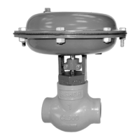
Details the Fisher D2 FloPro control valve, its design features, and suitable applications.
Presents a comprehensive table of technical specifications for the D2 FloPro control valve.
Crucial safety warnings and cautions to ensure safe installation and prevent hazards.
Step-by-step installation guidance and important notes for proper valve installation.
Instructions for setting the flow adjuster to achieve desired flow rates for different actuator actions.
Procedure and safety for converting the actuator from air-to-open to air-to-close.
Specific safety warnings related to changing the actuator's operating action.
General notes on valve maintenance, inspection frequency, and parts replacement.
Essential safety warnings and cautions for performing maintenance on valve trim components.
Critical safety information and warnings to be observed during the disassembly process.
Instructions and cautions for the correct reassembly of valve and actuator components.
Warning about using only genuine Fisher parts to maintain warranty and safety.
Overview of available parts kits and the detailed parts list for the valve assembly.
Specific maintenance procedures for packing constructions with older lot numbers.
Safety warnings and cautions pertinent to maintenance activities in Appendix A.
Notes and warnings related to ordering parts for older packing constructions.
Details on parts kits and the parts list specific to Appendix A.
The Fisher D2 FloPro Control Valve is a compact and robust valve designed for on-off control across a variety of fluid applications, capable of handling pressures up to 155 bar (2250 psig). It is particularly well-suited for use as a dump valve in gas separators and scrubbers, and also finds application in other high-pressure natural gas production, compression, and processing scenarios. The valve features threaded end connections and is available in an NPS 1 globe style valve body.
The D2 FloPro control valve operates as an on-off valve, meaning it is designed to either fully open or fully close to control fluid flow. Its primary function is to manage the flow of various fluids in high-pressure environments. The valve's design, including its FloPro flow adjuster, allows for precise control over the flow rate. The actuator, which can be configured as either air-to-open or air-to-close, utilizes a spring-and-diaphragm mechanism to drive the valve's operation. In an air-to-open configuration, increasing air pressure to the actuator opens the valve, while in an air-to-close configuration, increasing air pressure closes it. The FloPro flow adjuster, initially set at a 0.375 inch port flow rate position from the factory, can be adjusted to achieve different desired flow rates, offering flexibility in process control. The valve's shutoff classification is Class IV ANSI/FCI 70-2 and IEC 60534-4, indicating its capability for tight shutoff.
The D2 FloPro valve is designed for straightforward installation and operation. It can be installed in any orientation unless specific seismic criteria dictate otherwise. A standard flow direction is indicated by an arrow on the valve body, guiding proper pipeline integration. For continuous operation during inspection or maintenance, a three-valve bypass around the control valve assembly is recommended.
A key usage feature is the adjustable FloPro flow adjuster, which allows users to modify the valve's flow rate. This adjustment involves loosening socket head cap screws and repositioning the flow adjuster halves to the desired flow rate position, as illustrated by different flow rate settings (e.g., 0.5 inch, 0.375 inch, 0.25 inch). This adaptability makes the valve suitable for applications where varying flow capacities are required.
The actuator's action can also be changed from air-to-open to air-to-close, or vice versa, providing versatility to match specific control system requirements. This involves a detailed procedure of disassembling and reassembling the actuator components, including springs, diaphragm, and casings, to reverse the operational logic. This flexibility ensures the valve can be integrated into diverse pneumatic control schemes.
The valve is equipped with ENVIRO-SEAL™ D2 packing, a feature designed for environmental protection and reliable sealing, which is particularly important in high-pressure applications to prevent leakage of process media. A safety vent hole in the bonnet neck of the valve body serves as a critical safety feature, indicating if process pressure is trapped within the valve body during disassembly, thereby preventing sudden release of pressure.
The D2 FloPro control valve is designed for maintainability, with many operations possible while the valve remains in the line. Regular inspection and replacement of parts subject to normal wear are crucial, with frequency depending on service conditions.
Valve trim maintenance involves isolating the valve from line pressure, releasing and draining process media, and then disassembling the bonnet from the valve body. During this process, the valve plug and seat ring are inspected for wear or damage. If the seat ring is damaged, it can be removed and replaced, along with a new seat ring gasket. The valve stem and valve plug are also inspected for wear, and replacements can be made by unscrewing the old components and installing new ones. Proper torque values are specified for reassembly to ensure secure and leak-free connections.
Packing, valve trim, and actuator maintenance procedures are detailed to guide users through disassembly and reassembly. For packing replacement, specific instructions are provided for installing anti-extrusion washers, packing spacers, packing rings, and Belleville springs in the correct order. The use of a single-use packet of high-performance fluorinated grease is specified as the only acceptable lubricant for the D2 packing, emphasizing the importance of using appropriate materials for optimal performance and longevity. The packing retainer is torqued to a specific range and then loosened slightly to ensure proper compression and sealing.
Actuator maintenance involves disassembling the upper and bottom casings, springs, diaphragm, and associated components. The diaphragm is inspected for wear or damage and replaced if necessary. Reassembly procedures are meticulously outlined, including the correct placement of springs, washers, O-rings, and the diaphragm, along with specific torque values for hex nuts and cap screws. The importance of following the correct sequence for removing casing cap screws is highlighted as a safety measure to prevent personal injury or property damage due to compressed springs.
Throughout maintenance, warnings are provided to emphasize safety, such as wearing protective gear, isolating the valve from pressure, and using lockout procedures. The safety vent hole is a critical indicator during disassembly, and users are warned to stop immediately if process media escapes, indicating trapped pressure. The manual also stresses the use of genuine Fisher replacement parts to maintain warranty, performance, and safety.
| Manufacturer | Emerson |
|---|---|
| Product Name | Fisherr D2 FloPro |
| Category | Control Unit |
| Model | D2 FloPro |
| Input Signal | 4-20 mA, HART |
| Output Signal | 4-20 mA |
| Power Supply | 24 VDC |
| Communication Protocol | HART |
| Enclosure Rating | IP66 |
| Operating Temperature | -40 to 85°C (-40 to 185°F) |
| Mounting | Panel Mount |