Chapter 1 - General Description User Manual
N
N
e
e
t
t
w
w
o
o
r
r
k
k
P
P
o
o
w
w
e
e
r
r
S
S
w
w
i
i
t
t
c
c
h
h
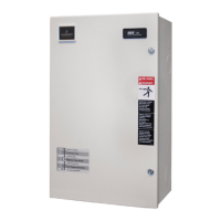
Operating Network Power Switch in Bypass mode
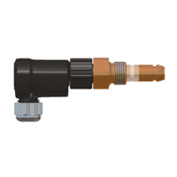
• Insert the Hot swappable module into the Network Power Switch unit
• Lock the sliding module for preventing its accidental opening.
• Unlock the Manual Bypass Switch with the key provided
• Connect the Load output to Network Power Switch by changing the switch position to Network Power
Switch output.
• Depending on the priority switch, Load will get transferred to source-1, if the priority switch is on source1.
• The Static Switch output position LED will glow
1.6 Potential free contacts
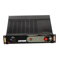
The Network Power Switch status can be checked with the 37 pin D-type connector, located on the rear end. This is a
potential free contact, and gives following indications as shown in Table 1-1 –
Table 1-1
191837363517Unsy nc h
193416151433S2 Feed
191332313012S2 Healthy
19291110928S1 Healthy
1982726257S1 Feed
192465423Priority
192132120Overload
CommonNONCCommonNONC
Termination available of 37 pin D-type connectorStatus
191837363517Unsy nc h
193416151433S2 Feed
191332313012S2 Healthy
19291110928S1 Healthy
1982726257S1 Feed
192465423Priority
192132120Overload
CommonNONCCommonNONC
Termination available of 37 pin D-type connectorStatus
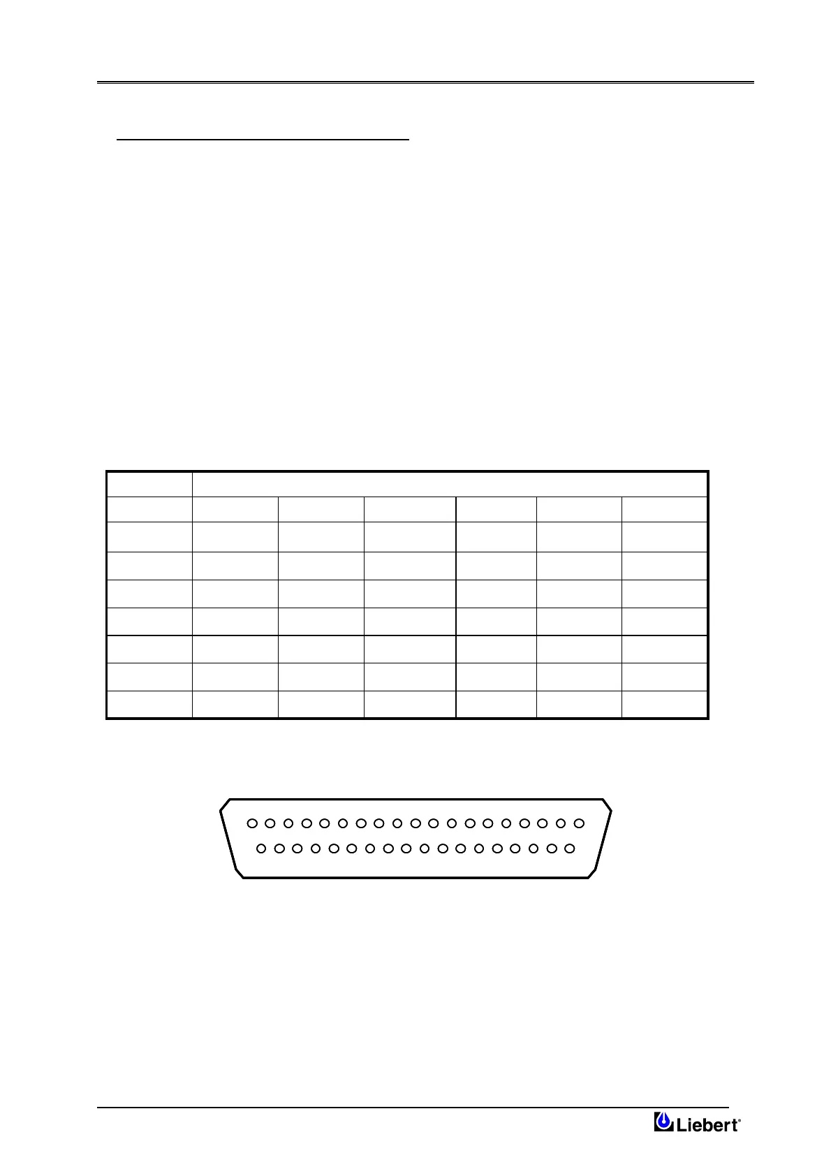
The pin details for this connector is shown in fig 1.6
1219 3456789101112131415161718
2037 21222324252627282930313233343536
1219 3456789101112131415161718
2037 21222324252627282930313233343536
Fig 1.6 – Pin details for 37 pin D-type Connector
Page 1-6 (03/04)