3. Ceiling Fan Assembly (Continued)
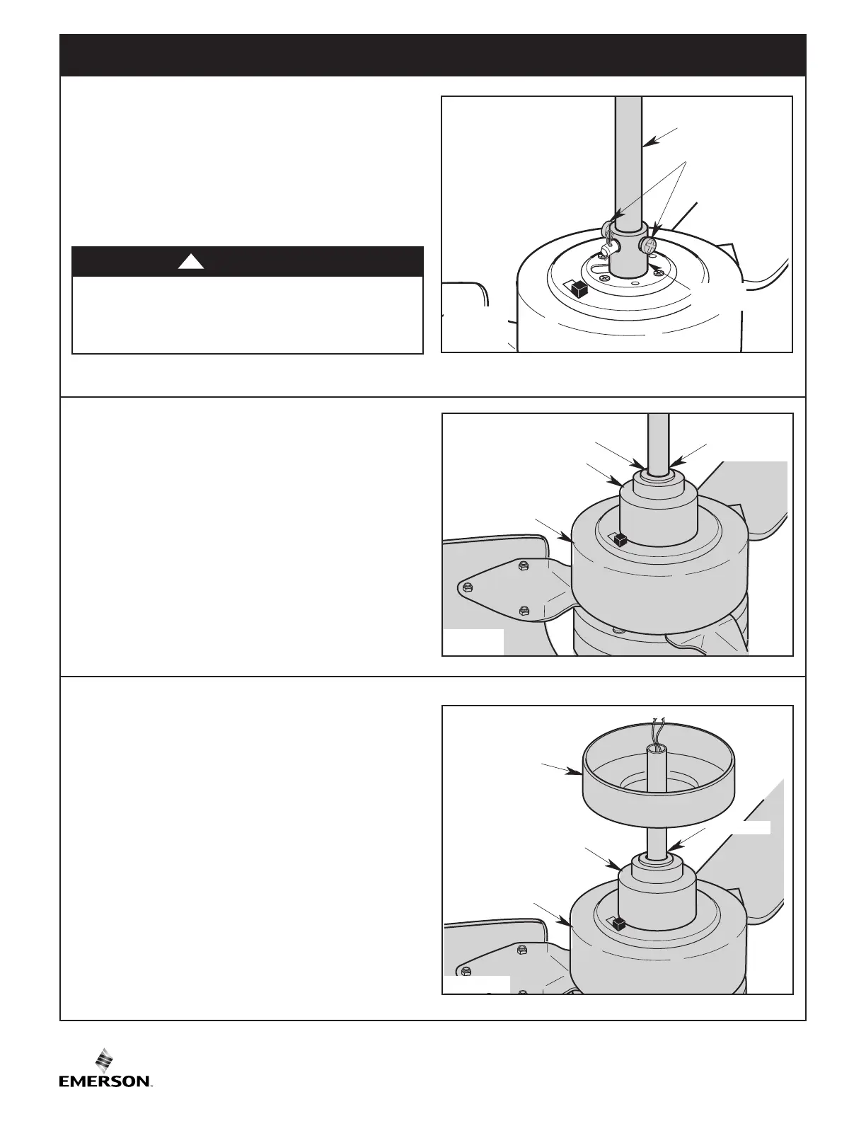
MOTOR COVER
DOWNROD
MOTOR COUPLING
COVER
6" DOWNROD
MOTOR COUPLER
COVER
GROMMET
Figure 8
3.8
Make sure the Grommet is properly installed in the
Motor Coupler Cover.
Slide the Motor Coupler Cover on the Downrod until it
rests on the Motor Cover (Figure 8).
Be sure the Motor Coupler Cover is oriented correctly
(Figure 8).
8
U.L. Model No.: CF765-1
MOTOR COVER
CEILING COVER
DOWNROD
MOTOR COUPLING
COVER
MOTOR COUPLER
COVER
Figure 9
3.9
Place the Ceiling Cover over the Downrod and let it rest
on the Motor Coupler Cover.
Be sure the Ceiling Cover is oriented correctly
(Figure 9).
DOWNROD
MOTOR
COUPLER
RETIGHTEN TWO
PHILLIPS HEAD
SET SCREWS
Figure 7
3.7
While pulling up on the 6” Downrod, reinstall and
tighten the Two Set Screws (previously removed) in
the Motor Coupler to secure the Downrod into place
(Figure 7).
NOTE: The set screws must be properly installed as
described above, or fan wobble could result.
It is critical that the set screws in the motor coupler are
properly installed and securely tightened. Failure to
verify that the set screws are properly installed could
result in the fan falling.
WARNING
!



 To Next Page