
C
Christina EvansJul 31, 2025
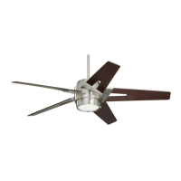
What to do if my Emerson CF430BS00 Fan will not start?
- DDawn KiddJul 31, 2025
If your Emerson Fan isn't starting, there are several things you can check. First, examine the main and branch circuit fuses or circuit breakers. Then, check the line wire connections to the fan and the switch wire connections in the switch housing. Finally, make sure the reversing switch is completely to one side, not in a neutral position.