6
ETL Model No.: CF955L
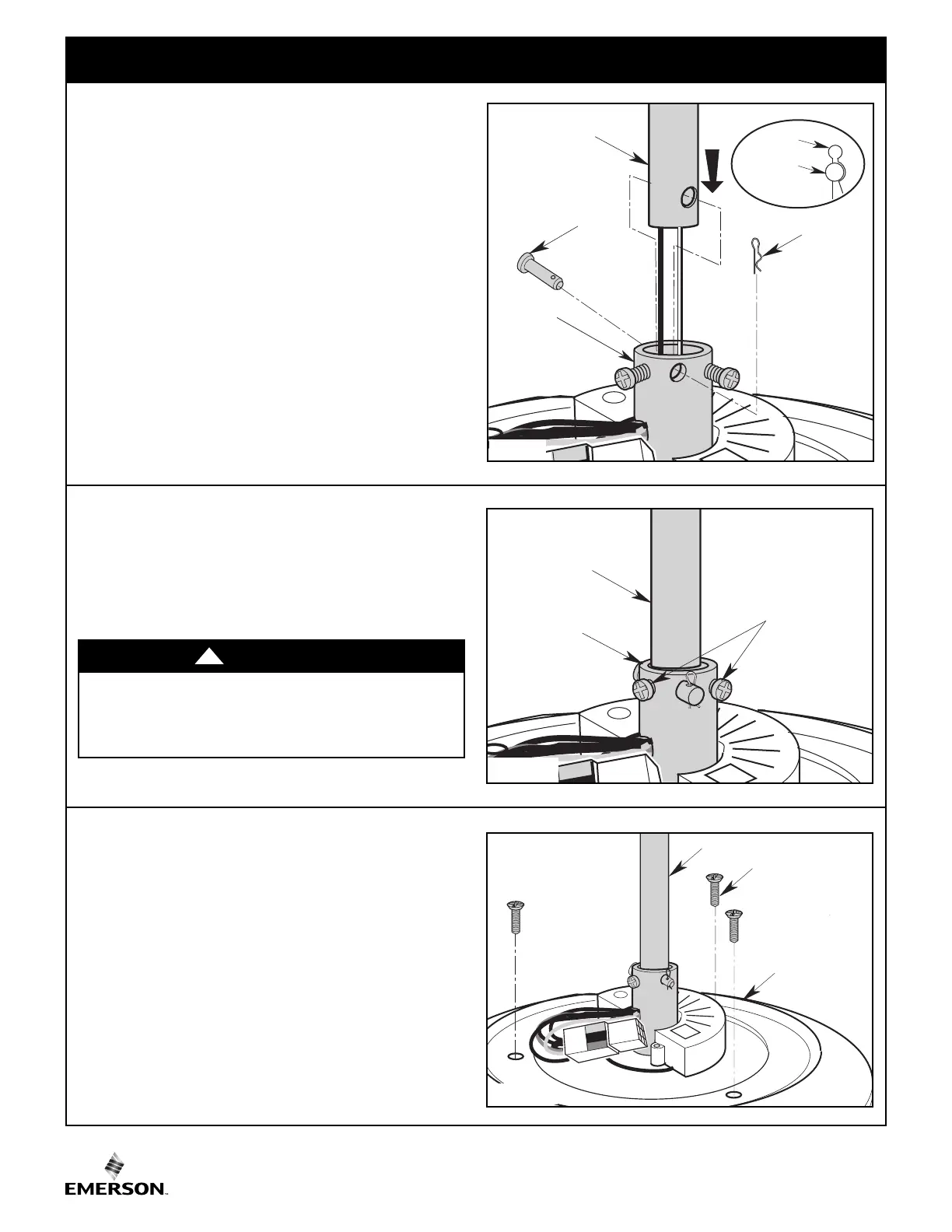
3. Ceiling Fan Assembly (Continued)
MOTOR
COUPLER
DOWNROD
RETIGHTEN
SET SCREWS
Figure 5
3.5
While pulling up on the downrod, securely tighten the two
Phillips head set screws in the motor coupler (Figure 5).
NOTE: The set screw must be properly installed as
described above, or fan wobble could result.
HAIRPIN
CLIP
MOTOR
COUPLING
DOWNROD
CLEVIS
PIN
HAIRPIN
CLIP
CLEVIS
PIN
Figure 4
#8-32 x .75" FLAT
HEAD SCREWS (3)
DOWNROD
FAN ASSEMBLY
Figure 6
3.6
Remove and retain the three #8-32 x .75” flat head screws
pre-installed on top of the fan assembly. (Figure 6).
3.4
A
lign the clevis pin holes in the downrod with the holes in
the motor coupler.
I
nstall the clevis pin and secure with the hairpin clip
(Figure 4).
The clevis pin must go through the holes in the motor
coupler. It is critical that the clevis pin in the motor coupler
is properly installed and securely tightened.
It is critical that the clevis pin and set screws in the motor
coupler are properly installed and securely tightened.
Failure to verify that the pin and set screws are properly
installed could result in the fan falling.
WARNING
!
 Loading...