7
emersonfans.com
Please contact 1-800-654-3545 for further assistance
ETL Model No.: CF955L
3. Ceiling Fan Assembly (Continued)
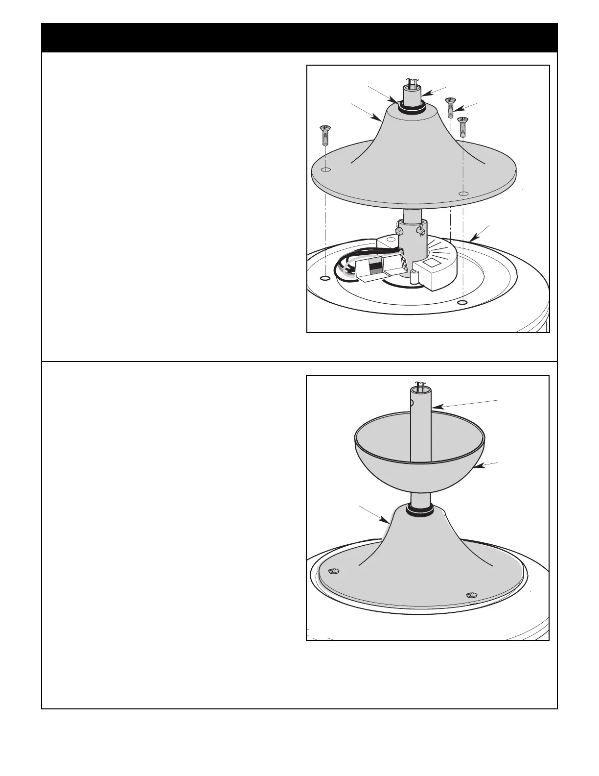
COUPLER
COVER
CEILING
COVER
DOWNROD
Figure 8
3.8
Place the ceiling cover over the downrod.
Be sure both the ceiling cover and the coupler cover are
oriented correctly (Figure 8).
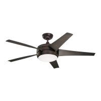
FAN ASSEMBLY
#8-32 x .75" FLAT
HEAD SCREWS (3)
GROMMET
C
OUPLER
COVER
DOWNROD
Figure 7
3.7
M
ake sure the grommet is properly installed in the coupler
cover then slide the coupler cover on the downrod until it
rests on the fan assembly.
R
einstall the three #8-32 x .75” flat head screws, removed
in Step 3.6, through the coupler cover and into the fan
assembly (Figure 7).
A spare #8-32 x .75” flat head screw is supplied in the
loose parts bag, if required.
 Loading...